To connect the TV to cable TV or an antenna, you need to purchase a special TV cable and put F-plugs on its ends.
With an illiterate solution to this simple task, the TV, when receiving both analog and digital signals, may work unstable or with poor image quality due to signal losses in the cable and its connections.
TV cable selection
Even a great TV and correctly fitted F-plugs to the ends of the cable will not be able to provide a high quality image on the screen when using a low-quality TV cable. And the question arises, what kind of antenna cable is better for connecting a TV and by what criteria to choose it?
TV cable device
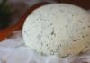
Consider how a modern television coaxial cable is arranged using the example of a CAT-703 cable.

In the center of the entire length of the coaxial cable runs a copper or steel wire core coated with a copper layer. This core is covered with a layer of insulation made of a dielectric material. A shielding copper or aluminum foil braid is put on the insulation, which acts as a second conductor. To protect against mechanical and climatic influences, the cable is covered with a hermetic protective sheath.
In inexpensive cables, only aluminum braid is used, in budget ones - copper, and in expensive ones - aluminum and copper at the same time, as shown in the photo.
How does current flow through an antenna cable?
To consciously choose a good antenna cable, you need to imagine how high-frequency current flows. The current in the electrical network flows over the entire cross section of the conductors.
The high-frequency current of the television signal flows according to a different law. Everyone knows how the laundry is wrung out in the centrifuge of the washing machine: the higher the speed, the stronger the centrifugal force acts on the water, and it is better removed from the laundry, the laundry becomes drier. On their own bodies, many have experienced the effect of centrifugal force while riding a carousel in childhood.

Similarly, the high-frequency current of the television signal flows in the antenna cable. The higher the frequency, the closer to the surface of the conductor it flows. The skin effect appears. If we take, for example, a copper wire with a diameter of 10 mm and a tube of the same diameter made of copper with a wall thickness of 1 mm, then a current with a frequency of 1000 MHz will flow through them with the same losses!
Therefore, in antenna cables used for military and space equipment, in order to reduce signal loss (attenuation), the central core and cable braid are often covered with a thin layer of silver and even gold. This is a very expensive pleasure, and such cables are not used in everyday life.
Due to the small size of the television signal in the antenna cable and its high frequency, it is not possible to determine the presence of it in the cable, and even more so to take measurements at home without specialized expensive devices. Only connecting the antenna cable to the TV will determine the presence and quality of the television signal.
TV cable marking
The most widespread on the market are antenna coaxial cables from different manufacturers with a wave impedance of 75 ohms of the brands RG 6U, SAT 50, SAT 703B and DG 113, which can be successfully used to receive an analog and digital television signal up to its transmission from a satellite dish with a frequency of up to 2, 15 GHz. The brands are given in ascending order of the quality of the antenna cable - reducing signal loss (attenuation) during transmission. Marking (designation) is necessarily applied to the sheath of the antenna cable along its entire length every meter with a digital mark of the footage.

This marking of the antenna cable means the following:
- CABLETECH is a manufacturer of CABLETECH (China).
- RG 6U/48 - cable brand.
- HIGH QUALITY COAXIAL CABLE - high quality coaxial cable.
- 75 OHM - impedance 75 ohms.
- 055M - meter mark, with each meter the mark changes by 1.
How to choose an antenna television cable
The antenna cable sheath must be marked as shown above. The antenna cable must have a wave impedance of 75 ohms (all TVs and switching devices - amplifiers, splitters) are designed for such impedance. The outer diameter of the antenna cable sheath must be at least 6 mm. Central core and shielding braid made of electrotechnical copper. These requirements are met by antenna cables of the SAT 703B and DG 113 brands. In the RG 6U cable, the central core is steel, electroplated with copper, the screen is made of aluminum foil and the copper alloy braid, this is a budget option.
It is not possible to describe all the existing television antenna cables, but the information provided is enough for everyone to make their own choice.
How to install the antenna plug on the cable
There is no need to invite specialists in order to connect the TV to the antenna cable. This work can be done by each home master on his own with the help of an improvised tool, if he follows the instructions below.
The voltage of an analog or digital television signal in an antenna cable is millionths of a volt, so an antenna cable connected to a cable network or another TV is not dangerous to humans. You can easily cut the cable without disconnecting its second end from the splitter or TV. An accidental short circuit between the center conductor and the shielding braid is not dangerous when cutting the cable.
How to install an F-plug on an antenna cable
The plugs are sold in three standard sizes for antenna cables of different diameters. When purchasing, please note that the F-plug is suitable for your TV antenna cable. This type of plug is suitable for analog, digital TV and satellite signals.
You can screw the F-plug onto the cable by cutting it in two ways, with the shielding braid twisted, in the diagram on the left side, and without wrapping it, in the diagram on the right, in accordance with the cutting diagram below.

The F-plug will be more secure if the shielding braid is twisted, but if you can’t wind it up, you can use the second method.
To cut a television cable, not by pressing the knife hard, so as not to damage the shielding braid of the antenna cable, its outer sheath is cut along several centimeters.

After the incision of the shell, it is folded to the side and cut off at the beginning of the incision.

The aluminum foil and copper braid are turned away. The screen in antenna cables comes in three versions: one copper braid, aluminum foil and a copper braid on top of it (as in my case), only aluminum foil.

Many do not know that to give mechanical strength the foil is coated on the inside with polyethylene. It is impossible to clean plastic. If you screw the plug onto the inside of the foil of the antenna cable, then there will be no contact, or it will be very poor. To prevent this from happening, you need to bend the half of the unfolded foil back, then the conductive side will be outside.
There are situations when the diameter of the female thread hole F of the plug is larger than the diameter of the antenna cable. In this case, several layers of insulating tape must be wound around the antenna cable before turning the foil in order to adjust the size of the cable. Then do everything as described. The insulation is removed from the central core according to the technology described in the article "Preparing wires for installation".

The F plug “wrap on cable” is screwed onto the foil.

The central core of the antenna cable is bitten off so that about 2-3 mm remains to protrude.

The second half of the plug is screwed up to the stop, and the F-plug is ready for use.

There are cases when, after inserting the antenna plug into the TV socket, the cable has to be bent at a right angle or it is not possible to install the TV close to the wall due to the interfering antenna cable. In this case, you can use the F-socket - angled plug.

The difference between the two plugs described is only in their shape. The technology for installing straight and angled plugs on a television cable is the same.
How to install an old design plug on an antenna cable
Before the advent of antenna F-plugs, plugs of a different design were used, which also did not require soldering, but were connected to the antenna cable using their own technology.

Before proceeding with the installation of the plug on the antenna cable, holding it by the metal part, unscrew the plastic housing by turning it counterclockwise. Then put the case on the cable so as not to forget.

The next step is to prepare the antenna cable for installation. To do this, with a knife blade, you need to cut through its outer shell with a slight pressure to a length of about a centimeter. Next, remove the sheath and cut the shielding braid by 5 mm. Remove five millimeters of central core insulation. The antenna cable is now ready to be plugged into the plug.

When filling the cable into the plug, it is necessary to exclude the contact of the conductors of the braid of the fasteners of the central core. Pliers crimp the petals of the antenna plug around the shielding winding. You don't have to put in a lot of effort. The main thing is to have reliable contact.


The last step is to screw the plastic part onto the metal part of the plug and insert the plug into the TV socket.
Soviet-era antenna plugs are slowly becoming a thing of the past, but millions of TVs are still connected using them. In the event of a cable replacement or poor contact in the plug, it becomes necessary to solder it.

Soviet plugs were tinned according to the requirements of GOST. According to these requirements, the solderability of tinned contacts was at least six months, so it was often almost impossible to solder cable conductors to the terminals after a year. The solder rolled off, and the surface of the plug turned black.
To obtain a reliable connection, you need to clean the soldering points to a brass shine. First, clean the end of the central contact with a flat file, and then with the sharp end of the file, as far as possible, turning it, clean the hole of the central contact. Then clean the terminals for soldering the cable shield with sandpaper or a file and tin them.

The next step is cutting and preparing the end of the antenna cable for soldering. The plastic part of the plug is immediately put on. Further, the upper sheath of the cable is cut along and removed to a length of about three centimeters using the technology described above. The shielding braid is untwisted, divided into two parts and the conductors are twisted. The insulation is removed from the central core so that it remains visible for two millimeters.

Before threading the antenna cable into the plug, its central core is shortened by a few millimeters to make it easier to thread the shield wires. Contact petals are slightly bent to the sides. The shielding conductors are threaded through the holes in the contact lobes until they stop, and the central core is threaded into the central contact of the plug. The petals are pressed tightly against the cable.

Shielding conductors at the point of passage through the holes of the petals are developed, and soldering is performed. The solder layer should be small, otherwise the plastic sleeve of the plug may not be put on. If the soldering turns out to be thick, then the excess solder can be ground off with sandpaper or a needle file during assembly. The excess length of the braid is cut off with wire cutters, but you can not cut it off.

Before soldering the central core, holding the plug by the metal part, pull the cable with force. This is necessary to eliminate the load on the central core if someone decides to remove the plug from the TV connector by the cable. Next, the central core of the cable is soldered from the outside and cut off. If solder icicles are obtained during soldering, they must be cut off with a knife blade or filed off.

It remains to check whether the latch tab is bent enough, and put a plastic cartridge on the metal part of the antenna plug until the latch snaps into place.
Where to insert the antenna cable on the TV
After the cable is plugged in, you can connect it to your TV. The socket for connecting the TV to an antenna or cable network is usually located on its back wall and is marked next to it in the form of the abbreviated inscription "ANT".

In the photo on the right side of it you can see the socket for connecting the antenna. The socket is special, standard and different from all other sockets and sockets available on the patch panel. Therefore, it is physically impossible to mistakenly insert the antenna plug into another socket. Any of the connectors, the installation of which is discussed in the article above, is well inserted into the TV jack.
In modern TVs, to receive a television signal, two connectors are installed to connect an antenna (cable television) and a satellite dish (receiver).

One, which is designated RF (ANT 1 IN), is designed to connect an antenna or cable network, this is installed on all TV models, both old and modern. The second one was recently installed, LNB (ANT 2 IN with external thread) is designed to connect a satellite dish.
If the TV supports the DVB-S2 standard, then the satellite dish can be connected without a receiver, directly to the LNB connector. To receive digital television channels from a television tower to an individual antenna, the TV must support the DVB-T2 standard. Therefore, when buying a TV, you need to pay special attention to the list of broadcast standards that it supports.
To receive a signal from a given connector, in the TV Menu, select the signal source as Antenna or Satellite TV and perform automatic or manual channel tuning.
How to connect an antenna cable to a TV without a plug
In life, there are situations when you urgently need to connect an antenna cable to the TV, but there is no plug or soldering iron at hand. You can temporarily connect the antenna cable without a plug. To do this, you must first remove the upper sheath to a length of 5 cm, develop and unscrew the shielding braid, remove the insulation from the central core of the cable and bend the core itself into a loop. The width of the loop should be slightly larger than the hole in the center socket of the TV connector.

If the connector on the TV is as in the photo, then you need to put an insulating tube on the central contact. Next, a loop is inserted into the central contact, and the shielding braid is tucked into the connector with a screwdriver blade. The main thing is to prevent the wires of the shielding braid from touching the central core of the cable.
If the braid is aluminum, then you can insert it into the TV connector and stuff thin copper wires taken from any stranded copper wire into the free space. To prevent the wire from falling out of the TV connector, you can fix it with a few toothpicks or matches. Such an impromptu connector will serve quite reliably.
How to connect an antenna cable to a crab without a plug
Cable preparation is exactly the same as for putting on an F-plug, the central core is inserted into the F-connector of the crab, and the screen is put on the protruding part of the crab connector and fixed with any wire or clamp. In extreme cases, you can fix the cable by tightly winding several layers of electrical tape. It will work no worse than with the F-connection.

If you use a clamp with a screw crimping device, then the quality and reliability of the connection will be no worse than with an F-connector.
Which antenna plug is better
The answer is unequivocal: the best of the three plugs considered for a television coaxial cable is the F-plug. This is easy to see in the photographs above, even without special knowledge.
As you can see, the antenna plug of the old design and the Soviet antenna plug have a small section of the central core of the cable that is not covered by a shielding braid. This violates the uniformity of the wave impedance, which leads to insignificant losses in the television signal.
The F-plug does not have an open section of the central core of the antenna cable. Another advantage of the antenna F-plug is the ease of installation. With a minimum set of standard tools, without skills, almost anyone can correctly put the antenna F-plug on the cable.
How to connect multiple TVs
to cable network or antenna
Connecting several TVs to a cable network or an antenna transmitting an analog or digital television signal is no more difficult than one, unless you have to put more than one F-plug on the cable. To do this, there are TV signal splitters, popularly referred to as "crab", they are also called "splitter", "splitter" or "divider".

The crab has one connector for connecting a signal from an antenna or a splitter in the entrance, marked IN (input), and several connectors for connecting TVs, marked OUT (output). If there is no marking, then usually the crab has an entrance on one side of the body, and exits in a row on the opposite side. All outputs for the crab to work properly must be connected to TVs.
If there are two outputs, then to two TVs, if there are three outputs, then to three, and so on. There should be no free connectors on the crab. If an unconnected output remains, then it must be loaded with a 75 ohm resistor. Or as they say, put a stub. But at the same time, part of the useful signal will be lost, it is better to use a crab, in which the number of taps is equal to the number of connected TVs.

The design of the splitter is a thin-walled case made of silumin or brass, in which connectors for connecting F-plugs are made at the same time. The divider circuit is usually transformer, one turn of enameled wire with a diameter of 0.2-0.4 mm, threaded through ferrite rings or tubes. Installation of transformers is carried out by hinged method. The case is hermetically sealed with a metal lid and sealed or fixed with glue.
Eyelets are provided for attaching the crab to the wall. The case also has a thread with a screw for grounding, although it is not clear where to get the ground wire in the vast majority of apartments. Usually they are not grounded, so pickups are possible on some channels from electrical wires, the Internet, a telephone passing next to the television cable. If possible, when laying the cable, such proximity should be avoided. For a more detailed acquaintance with the design and electrical circuit of the crab, you can visit the page "How to connect an antenna television amplifier to the power supply".
If there is a desire, then a crab, which is not inferior in technical parameters to expensive samples of well-known companies, can be made by hand.
When connecting TVs through a crab, the TV signal level reaching each TV connected to it, regardless of whether the TV is working or not, will decrease due to losses in the crab and additional cable length. When connecting two TVs - by 30%, three - by 60%, four - by 90%, and if the analog or digital television signal coming to the crab is already weak, then the image quality on all connected TVs can be significantly reduced. Usually, the signal in cable TV is strong enough, and its level is enough for the normal operation of all TVs connected to the crab.
How to connect the antenna cable
to the TV signal line at the entrance of the house
Usually, a television cable is laid along the roof of the house and then, after amplification with a main amplifier, it branches along the entrances of the house. Since there are different packages of television programs, at the entrance to the entrance the cable is branched using a filter crab, which is a crab with two outputs. From one output, the signal comes out unchanged, and from the second output - cut off by a high-frequency filter. Thus, the ability to watch all TV channels for those who buy cheaper social packages is limited. Therefore, two cables pass down the entrances.
If you examine the walls in your entrance, you will definitely find a metal box on each floor, from which television antenna cables go to the apartments. In modern houses, boxes are no longer installed, but everything is placed in wall cabinets, in which case you will see a metal door with a lock. These boxes contain subscriber couplers of the television signal. If you remove the lid from the box or open the cabinet door, you will see something like this. In the photo on the left is a coupler for subscribers of the full package of television programs, and on the right for subscribers of the social package.

By law, taps must be fixed and grounded, but cablemen do not do this to simplify the work. Perhaps this is better, because if the grounding is of poor quality, then such grounding can create interference.

Taps installed in junction boxes are not fundamentally different from crabs for connecting multiple TVs, but they work a little differently. One F connector is used to connect the cable coming from the IN trunk (Input). The second OUT is for signal transmission to the next coupler installed one floor below. The remaining F connectors TAP (TAP), there can be from one to five, are designed to connect subscribers, that is, to connect television cables going to apartments.

There should be no unconnected subscriber connectors. In case of disconnection of one subscriber, for example, for non-payment, it is allowed to install an F-connector with a load resistance of 75 Ohm instead of a cable. If you want to connect a new subscriber to a cable television network, then the splitter for two subscribers, as in this example, is replaced by a three-terminal one.
Thus, to connect the TV to the cable network, a piece of television cable of the required length with antenna F-connectors installed at the ends is sufficient. One F-connector of the antenna cable is connected to the subscriber coupler in the entrance, and the second - to the TV.
What is the difference between a crab and a coupler
In a crab, the power of the incoming television signal is usually divided equally among all connected televisions. Unlike a crab, in a coupler, only a small part of the signal power entering the input, about 6 dB, is allocated to subscribers.
To ensure a sufficient level of the television signal coming to the subscribers, the signal to the input of the coupler is supplied from the main power amplifier, depending on the number of connected subscribers. Together, all the taps installed in one entrance represent a crab with numerous branches.
TV Signal Amplifier
If, after installing the crab, the image has become unsatisfactory, then you will have to additionally put a television amplifier in front of it. The amplifier is arranged in the same way as the crab, but in its case, active elements (transistors or a microcircuit) are additionally installed that amplify the video signal. For a television amplifier, an additional supply voltage is required, and this must be taken into account when choosing a place for its installation.
The television amplifier should be installed as close as possible to the source of the television signal, since the amplifier amplifies noise along with the useful television signal. The photo shows a television amplifier TERRA HA123, designed to work in a home television network, having one output, with the ability to adjust the gain from 8 to 28 dB. If possible, then the ideal option is to place the amplifier directly in the box of the main signal splitter for apartments.

If the TVs are located not far from the TV amplifier, then it is more expedient to install only one TV signal amplifier with several outputs instead of the TV amplifier and the crab. For example, a television amplifier-splitter model Televes 5523 (Spain), having a gain of 16 dB and five outputs, which makes it possible to connect up to 5 TVs to it.

If the signal is taken from an individual antenna, then there are amplifiers that are designed to be installed directly on the antenna instead of a matching loop. Antenna amplifiers provide high-quality reception at a distance from the transmitting antenna up to 100 km.

The antenna amplifier, depending on the signal level at the antenna installation point, must be selected according to the gain factor for each specific case. The supply voltage for such amplifiers is supplied via a coaxial cable.
Fight against interference
installation of a ferrite ring on the antenna cable
Sometimes, after connecting several TVs to cable TV using a crab, interference may appear on some channels in the form of random white or black dots, traveling waves, or a grid across the screen. This happens when a high-frequency interference signal from a local oscillator, parallel-connected TVs or other sources of interference enters the antenna input of the TV. The penetration of interference from TVs connected in neighboring apartments is not excluded. The level of this kind of interference can be significantly reduced or even completely eliminated by installing a ferrite ring on the cable.

The effectiveness of interference suppression with a ferrite filter depends on the cross-sectional area of \u200b\u200bthe ring: the larger its area, the greater the inductance of the made inductor. The ferrite ring put on the antenna cable forms a choke and, together with the linear capacitance of the antenna cable, forms a U-shaped high-frequency filter. Maximum interference suppression will be achieved when two rings are installed on the antenna cable at its ends.
Ferrite rings are sold in stores and come in two types: one-piece and consisting of two halves, pressed into a plastic case with latches. But you can do without extra costs. If you look closely at the interface wires going from the system side of the computer to the printer, scanner, monitor and other peripheral equipment, you can see a thickening of the cylindrical cables. These are ferrite filters.

Surely you have an old kinescope monitor gathering dust or have unnecessary interface cables. It is enough to cut the plastic with a knife, remove the ferrite ring and install it on the antenna cable. After installing the ferrite ring, interference on the TV screen will no longer interfere with watching TV programs.
Quite often, one family has two or even 3 TVs, but the antenna is still the same. Many home masters have a natural question: how to connect several TVs to one antenna, given that they are all in different rooms. This can only be done using a special TV signal splitter or splitter.
In strict technical terms, this is a device that consists of a set of resistances designed to match the wave reactance of the antenna feeders and several television receivers. The splitter, in addition to a stable connection, guarantees the support of a passing signal with minimal attenuation.
On sale, you can pick up a splitter for two TVs, and if you need to connect 3 TVs, then you need to choose splitter with three outlets.
Advice! When using a splitter for 3 outputs, three TVs must be connected, if less, then a 75 Ohm ballast resistor is connected to the free port, which ensures the normal operation of the splitter.
When choosing such a device in a store, first of all, ask the seller the frequency range that he passes, so that when installing the line on 3 TVs, there will be no problems with the signal. Detailed information is also in the instruction manual of the device.

Splitter "crab"
The design of the splitter (its popular name CRAB) is enclosed in a durable body made of brass or silumin(90% aluminum and 10% silicon), which is not subject to corrosion, but is much lighter than stainless steel. Outside there are connectors for connecting F-plugs: on the one hand for the antenna, and on the other two or more - this is the connection of TVs. Its scheme is quite simple, usually transformer: one turn of enameled wire with a cross section of not more than 0.4 mm, which is threaded into rings or ferrite tubes. The body is closed with a lid, which is soldered or fixed with high-strength glue to enhance the tightness.
How much we connect TV
Before connecting and final assembly of the entire line, it is necessary to specifically determine the number of connected TVs. How to connect two TVs to a satellite dish is one question, but if you need 3, then the circuit will be slightly different and the splitter is used with three outputs. In addition, it is necessary to take into account the attenuation of the signal, which increases with increasing receivers:
- 1 TV - signal power is 1/1;
- two - signal 1/2;
- 3 - the power is only 1/3.
Therefore, when installing a line on three TVs or more, a signal amplifier is installed. Specialty stores offer a wide variety of these products with features that allow you to make connections without loss of image quality.

We collect the connection diagram
Consider the option of connecting two TVs, one of which is in the living room, and the second in the nursery. We will use an antenna splitter or splitter that splits the main signal to 2 TVs. To carry out the work, modern equipment is used, so we do not need a soldering iron, tin and rosin.
The splitters of the new sample are used screw sockets: a previously stripped one end of the cable is inserted into the nut, and the second with a similar plug will subsequently be connected to the TV. The central core must be inserted into a special hole in the splitter screw socket, and the nut is wrapped and tightly presses the copper braid of the cable to the device body.
Before starting work, disconnect the products from the network until all work on connecting TVs to one satellite dish is completed.
Step-by-step instruction:

The figure shows the connection diagram a) 2 TVs and b) - an option for 3 TVs.

How to amplify the signal
Many users complain that when they connected two TVs to one antenna (satellite or simple), the image got much worse. There is nothing unusual about this - the fact is that the splitter only splits the signal. To eliminate such a negative phenomenon, it is necessary to use a special television amplifier, which is almost similar to a crab, but there are resistors and a microcircuit.
It requires a separate power supply, so when installing it, you need to have an outlet or a carrier nearby.

TV amplifier
It is better to install the amplifier as close as possible to the antenna, and already make branches from it: for example, for our case, one branch goes to the living room and the other to the nursery. Experts advise in this case not to use a splitter, but to get by with installing an amplifier - it will cost more, but the signal quality will be high.
There is another option for getting rid of interference (and you can also improve the signal quality much) - put special ferrite rings. This can be done on the part of the cable that is not visible from the side, next to the connection to the antenna input to the TV. Such noise cutters are installed, for example, on the laptop adapter wire - a small cylindrical device on the cord next to the plug connecting the cord to the computer. There are other ways as well. Also, do not forget that the signal quality depends on the antenna itself, so you should know. If you have the skills to work with soldering equipment, then you can even make high-quality ones. And then you don't have to think why your .
Very often, a second TV appears in one family. In this case, there is only one antenna. The question arises: how to connect two TVs to one antenna? There are ways to use one antenna for two or more TVs.
What will be required
To connect, you need a few parts:
- two-output splitter (splitter). This is a device that allows you to split the signal from the antenna into two or more streams. It has an input on one side and two or more outputs on the other - for connecting television receivers.

- 5 connectors corresponding to the splitter;
- 2 adapter plugs;

- antenna cable.
Important: When purchasing a splitter, do not confuse the number of outputs! A three-way (three-output) splitter is used to connect three receivers, but not two! If, however, there is still a three-output at hand, then you can solve the problem by connecting a ballast resistor (resistance 75 Ohm) to the free output. And if there is a plan in the future to install and connect several TVs to this antenna, then it is better to immediately buy a splitter with several outputs and temporarily drown out the empty outputs with the same resistance.
Work progress
We will try to talk about the connection in such a way that even someone who does not understand radio engineering at all can cope with the task. Step by step it is done like this:
- Choosing details. The first step is to buy a splitter. They are different, including those that need soldering, and those that do not. If you know how to solder, then it is better to take those that involve soldering. This connection is always more reliable than any other, it gives less signal loss and preserves its quality.
If you do not have soldering skills, then you need to choose the appropriate splitter, as well as suitable for a particular type of cable. A win-win option would be a splitter with built-in jacks for coaxial cables.
After choosing a splitter, select the appropriate connectors. Now F-connectors are very popular due to the fact that they are reliable, easy to install.
- Choosing a place for a splitter. It is optimal to position the device so that the antenna cable can freely reach it and, if possible, have the shortest distance to both TVs.
- Cutting the existing antenna cable. It is necessary to cut so that the cable freely reaches the splitter. Together with a piece of cable, the old plug is cut off.
- Cable cutting and installationF– connector.

For those who know how to solder, it makes no sense to tell how to cut the cable and solder it to the splitter - they know it themselves. The following is written for the average user who is not familiar with the radio business.
So, we cut the cut end of the wire, as shown in the figure: we clean the edge, wrap the braid. The insulator of the middle core should protrude slightly, and the middle core itself should protrude at least 5 mm. A tool for dismantling insulation from a coaxial cable at home is an ordinary kitchen knife.
Important: The cable must be standard, more often the DG 113 or SAT 703B brands are used. In no case should the cable braid be connected to the central core, otherwise the signal will not pass at all.
Install F-connector. It is also called wrapping, because the connector is wound onto a soft wire. The connector for connecting the cable and the splitter is ready.
- Cut off two pieces of wire with the expectation that the length is enough for each TV.
- We mountF- connectors similarly for connecting TV cables and splitter outputs. Do the same on the other ends of the cables.
As a result, we have all five connectors involved, including:
- one from the antenna, to enter the splitter;
- two television, for exits from it;
- two television free.
- We connect the connectors to the splitter.


- We connect two free connectors with adapters. An adapter is a device on one end of which an F-connector is attached, and on the other end a coaxial plug for connecting to television receivers. Usually this device is referred to as a whole plug.
- We turn on the TVs. We check how both receivers work. If everything is done correctly, then the image should be normal. Now you can easily enjoy an excellent picture on two receivers at once, without interfering with each other.

According to the diagram below, you can see the path along which you need to connect 2 TVs to one antenna:

How to install an antenna with an amplifier
But what if the image quality deteriorated after connecting the splitter? This may mean that the antenna on two TVs does not provide the desired signal, while the separating device also takes some of it. The output can be an antenna with an amplifier, it is also called Polish. Such an antenna for two television receivers connected to the device will improve the signal quality in both televisions. For this you need:
- In an already existing circuit with a splitter put awayF- connector from the entrance to it.
- In his place plug in the power supply from the antenna kit with amplifier.
- At the entrance install an antenna adapter(the so-called "mother") and insert the plug from the antenna with the amplifier there.

This should improve the signal quality.
Splitter with amplifier
There is a second option - look for a splitter with a built-in signal amplifier. This method is good when the TV initially showed well and a new antenna is not required. However, before purchasing a new device, discuss your specific case with a specialist.
Amplifiers, including antenna amplifiers, have different gains, and too much signal is just as bad as too little and can also cause distortion. The telemaster will measure the signal level and give advice on purchasing an amplifier.
By the way, the problem with signal attenuation can even more arise if you connect several TVs to one antenna. The more receivers, the more the signal attenuates. Therefore, when planning to connect several television receivers, weigh all the pros and cons.

Below is a video instruction for connecting an antenna to two television receivers:
In contact with
The basic principle of the satellite receiver: one receiver - one TV. To play on the screens of several TVs one common channel will require a television modulator.
To connect two, four, eight TVs to the antenna, working independently of each other, you need to use a converter for two, four, eight outputs. If you need to connect more than eight TVs, then multiswitching is necessary. Multiswitching is also useful for connecting more than four TVs.
We select and supply antenna equipment throughout Russia!
Options for connecting TVs (receivers) to a satellite dish
Satellite dishes cannot be connected to TVs like terrestrial antennas using conventional dividers and couplers!
What are the characteristics of a satellite signal?
The satellite signal has two polarizations L and R for circular polarization, and V and H for linear polarization. Polarization in converters is switched by voltage +13V and +18V. In addition, channels with linear polarization have two more frequency ranges, the upper frequency range of the converters is switched on by a 22 kHz generator.
How to connect two receivers or TVs with CAM modules to a satellite dish
You can try to connect the antenna through a satellite splitter. But with such a connection, you can simultaneously watch channels in only one polarization and one range. If you connect Tricolor TV or NTV Plus according to this scheme, then some of the channels will be unavailable, and if you connect Telecard, then more than half of the operator’s channels will be unavailable, so it’s better not to use this connection scheme.
To connect to a satellite dish in this version, you need a converter for two outputs.
Fig.1. Scheme of connection through a satellite splitter.
How to connect four receivers or TVs with CAM modules to a satellite dish
The simplest connection option is to use converters for 4 outputs, in the same way you can connect three TVs, there are no converters for 3 outputs. If there are more than 4 TVs, then the diagrams in Fig. 3 are suitable for connection. and Fig.4. There are other connection options, they can be viewed in the "Satellite equipment connection diagrams" section of the site.
According to this scheme, you can connect NTV Plus, Tricolor TV, Telecard and MTS.

Fig.2. Option to connect to one satellite dish (dish) up to 4 receivers or TVs equipped with receivers.
Schemes for connecting satellite dishes Tricolor TV and NTV-Plus to eight or sixteen TVs

Fig.3. Option to connect one satellite dish (dish) to 16 TVs.
This scheme, in addition to satellite television, allows you to connect terrestrial television. If the TVs are not equipped with satellite receivers, then the antenna is connected to the TVs via external satellite receivers.
On Fig.3. a variant of connecting a satellite dish Tricolor TV and NTV-Plus is presented.
Why you can not connect a satellite dish to TVs (satellite receivers) through a TV divider
The answer is simple: from the converter, which is installed on the dish, the satellite signal of the first intermediate frequency is fed to the input of the receiver, which can be standalone or built into the TV design. In turn, a DC supply voltage is supplied from the receiver to the converter, in the range of 13-18 volts. But why such a voltage spread? A voltage drop is required to switch the polarization of the converter. Without going into the details of polarization, we note that if you watch television in one polarization, then half of the channels can not be seen. When several receivers are connected to one converter through a divider, each receiver outputs a voltage corresponding to the polarization of the switched on channel, for example, if 18 volts is supplied to the input of one receiver, then 13 volts from another receiver cannot be applied to the converter.To connect a large number of receivers to one satellite dish, multiswitches (electronic switching devices) are used.
Connecting a large number of TVs to one satellite dish using multiswitches
Multiswitches are: terminal and pass-through, with and without an additional power source, with and without a built-in on-air amplifier, designed for connection to converters with circular polarization or linear polarization, and so on. In addition, 1 or more converters, as well as 4 or more receivers can be connected to multiswitches. Multiswitches can be used in conjunction with amplifiers, couplers and other satellite distribution devices.
Description of the scheme for connecting one satellite dish to 16 TVs
Scheme in Fig.3. combines satellite and terrestrial television and allows you to connect at least 16 TVs. The terminal multiswitches used in it, powered by connected receivers, have two satellite inputs and are designed to connect converters with circular polarization, they are used to connect the most popular satellite operators: Tricolor TV and NTV-Plus.
The circuit uses two multiswitches, which makes it possible to connect 16 receivers. Both multiswitches are connected to a converter with 4 outputs, 2 outputs per multiswitch.
Multiswitches and a connecting cable introduce a certain attenuation into the satellite signal, therefore, to implement this scheme, it is desirable to use a dish size with a diameter larger than recommended by the operator, in the Volga Federal District - 0.9 m.
Connecting an on-air antenna to multiswitches
The Lumax MS-3801 multiswitches provide for the connection of an on-air antenna for distributing a TV signal to 16 TVs. As an antenna, a UHF antenna is used, designed to receive two packages of digital television and analog channels of the decimeter range. The circuit is designed to work in the zone of reliable signal reception, so an additional on-air amplifier is not used. The terrestrial signal coming from the antenna is divided by an ordinary terrestrial divider by two and enters the multiswitching inputs, where it mixes with the satellite signal, and then enters one common cable into each SAT-TV outlet. In sockets, using a built-in filter, the signal is divided into terrestrial and satellite. The terrestrial goes to the antenna input of the TV, which can be equipped with a DVB-T2 terrestrial tuner, and the satellite signal goes to the satellite input of the TV, equipped with a DVB-S2 tuner or to a separate satellite tuner.
Features of the application of the connection diagram shown in Fig. 3.
The presence of two multiswitches allows you to conveniently place equipment on two different levels, floors of the house, in order to significantly reduce the length of the cable web. The on-air part of this circuit only works when the satellite receiver is turned on or with an additional 18 volt power supply connected to one of the multiswitching outputs. Option to connect to a satellite dish six TVs with an independent terrestrial channel

Fig.4. Option to connect one satellite dish (dish) to 6 TVs.
Scheme in Fig.4. in addition to satellite TV, it also allows you to connect terrestrial television. If the TVs are not equipped with satellite receivers, then the antenna is connected to the TVs via external satellite receivers.
The scheme was drawn up for connecting the satellite dish Tricolor TV and NTV-Plus.
Scheme in Fig.4. does not differ significantly from the previous connection scheme, and the presence of elements for connecting only 6 TVs is explained by the greater clarity of circuit design. With great success, this circuit can easily be turned into a device for connecting 16 or more TVs.
The difference between the circuit shown in Fig. 4 and the circuit in Fig. 3 is that the on-air input of multiswitches is not used in it. It is no coincidence that built-in on-air multiswitching modules cannot provide high quality on-air TV signal conversion. The multiswitching amplifier has a high noise level, low gain, small gain dynamic range, and poor isolation from the satellite signal. To achieve high parameters of the on-air signal, it is necessary to use expensive multiswitches, and this is not always advisable, since the main task of multiswitching is to distribute a satellite signal to receivers.
On the diagram Fig.4. the terrestrial signal is formed by a separate channel, from the UHF antenna, the TV signal goes to the amplifier, antenna, if the useful signal level is low or apartment, if the signal level is not enough to distribute to a large number of TVs.
From each of the outputs of the multiswitching and the air divider, the signals are mixed using a TV-SAT diplexer, and then one cable is fed into each of the sockets, all as in the previous diagram.
This connection option is very popular with antenna installers, as it allows you to achieve good quality analog television signals at low cost.
Structurally, the scheme is as follows: a plate with a converter is installed on the street, the UHF antenna is also located on the street, next to it on the mast is an antenna amplifier, the power supply of the amplifier is in the attic. Three cables from the above devices are brought into the switchboard of the house. The devices of the circuit, circled in red, are installed in the switchboard of the house and from there the TV signals are routed through the sockets.

Fig.5. The appearance of a universal outlet.
The selection of terrestrial antennas and amplifiers is best left to specialists. If you have any questions related to the performance of the circuit, then you should also contact a specialist.
Several TVs in one apartment are not at all surprising these days, but as a rule, there is only one antenna for them.
In such a situation, a very appropriate idea appears, which is to connect TVs to one antenna.

But it will not work to make a high-quality connection without a signal divider or other device.
Cable splitter

This device matches TVs and antenna. The splitter allows you to send a signal of a high-quality type that does not fade and does not receive extraneous interference.
In the standard version of the splitters, you get only two outputs, but in more expensive models there may be more.
It is worth noting that when buying such a device, you need to pay attention to the signal range that this device can miss. More detailed information can be found in the instructions for the device.

The splitter, or as it was called in the common people CRAB, is enclosed in a very durable and interference-resistant case.
The case is not even subject to corrosion, and in comparison to strength, it is not much inferior to steel. Outside, you can see the antenna input and TV outputs.
The transformer-type circuit looks like an enameled wire, with a cross section of 0.4 millimeters. It is threaded into ferrite-type rings or tubes. A lid is attached over the entire structure, which creates tightness.

Number of TVs
Before starting the connection, decide on the number of TVs. If you decide to connect three TVs at once, then the operation scheme will be different than with one TV:

With each addition of a new TV device, the signal becomes less powerful for other TVs, but it is distributed evenly among all.

But this problem is easily solved by the amplifier. These days, stores are crammed with these devices, and the quality of the signal received from them in the rarest cases is a bit disappointing.
Splitter circuit
If you purchased a splitter in a store, then most likely you just have to insert the cords into the sockets and everything is ready, but it also happens that you need to do everything from scratch.

Installation instructions from scratch:

First of all, you will need a coaxial cable, the length of which will be approximately 10 - 15 meters, depending on the range of your TVs from the antenna.


Insert all plugs into the correct sockets. Next, you can connect the TV to the network and install channels. But if the signal quality on one of the TVs is low, you will need to crimp the cable again or look for a place to get interference.

We amplify the signal
Often, satellite TV users complain that when TV equipment is added, the signal loses its stability and quality.

But this is a very reasonable dissatisfaction, because the splitter does not amplify the signal, but divides it into power into active sockets.

By installing an amplifier, this problem will leave you forever. But it is best to do this near the TV.

In cases with interference, you can get by with ferrite rings, which are easy to purchase at the store or found on old microcircuits.


You can install the rings in any convenient place, the main thing is that they fulfill their purpose. These mini noise protectors are found on even the most modern cables.

Laptops, chargers, headphones, etc. are all equipped with such rings. Some create protection from the cables themselves for equipment, and some are used as signal storage.

Simply put, ferrite rings work both ways. Do not neglect them even in cases where your equipment is working properly. The fact is that even the smallest interference can become a real problem in the future, because they can make some of the elements of technology heat up.

After some time, the heated area may finally fail and the signal quality will disappear.

But if you install rings in all weakly protected or very high voltage places, then long-term problems can be avoided.


You should not remove the rings from the cable, even if you think that this cable is completely harmless to your equipment.

Photo examples of connecting several TVs to one antenna