The article describes how to build a three-phase (single-phase) 220/380 V generator based on an asynchronous AC motor. A three-phase asynchronous electric motor, invented at the end of the 19th century by the Russian electrical engineer M.O. Dolivo-Dobrovolsky, has now received predominant distribution both in industry and in agriculture as well as at home.
Asynchronous electric motors are the simplest and most reliable in operation. Therefore, in all cases where it is permissible under the conditions of the electric drive and there is no need for reactive power compensation, asynchronous AC motors should be used.
There are two main types of asynchronous motors: with squirrel-cage rotor and with phase rotor. An asynchronous squirrel-cage electric motor consists of a fixed part - the stator and a moving part - the rotor, rotating in bearings mounted in two motor shields. The stator and rotor cores are made of separate sheets of electrical steel isolated from one another. A winding made of insulated wire is laid in the grooves of the stator core. A rod winding is placed in the grooves of the rotor core or molten aluminum is poured. Jumper rings short-circuit the rotor winding at the ends (hence the name - short-circuited). Unlike a squirrel-cage rotor, a winding is placed in the grooves of the phase rotor, made according to the type of stator winding. The ends of the winding are led to slip rings mounted on the shaft. Brushes slide along the rings, connecting the winding with a starting or adjusting rheostat.
Asynchronous electric motors with a phase rotor are more expensive devices, require qualified maintenance, are less reliable, and therefore are used only in those industries in which they cannot be dispensed with. For this reason, they are not very common, and we will not consider them further.
A current flows through the stator winding, which is included in a three-phase circuit, creating a rotating magnetic field. The magnetic field lines of the rotating stator field cross the rotor winding rods and induce an electromotive force (EMF) in them. Under the action of this EMF, a current flows in the short-circuited rotor rods. Magnetic fluxes arise around the rods, creating a common magnetic field of the rotor, which, interacting with the rotating magnetic field of the stator, creates a force that causes the rotor to rotate in the direction of rotation magnetic field stator.
The rotational speed of the rotor is somewhat less than the rotational speed of the magnetic field created by the stator winding. This indicator is characterized by slip S and is for most engines in the range from 2 to 10%.
Most commonly used in industrial installations three-phase asynchronous electric motors, which are produced in the form of unified series. These include a single 4A series with a rated power range from 0.06 to 400 kW, the machines of which are distinguished by high reliability, good performance and meet the level of world standards.
Autonomous asynchronous generators are three-phase machines that convert the mechanical energy of the primary engine into AC electrical energy. Their undoubted advantage over other types of generators is the absence of a collector-brush mechanism and, as a result, greater durability and reliability.
Operation of an asynchronous electric motor in generator mode
If an asynchronous motor disconnected from the network is put into rotation from any prime mover, then, in accordance with the principle of reversibility of electrical machines, when the synchronous speed is reached, some EMF is formed at the terminals of the stator winding under the influence of the residual magnetic field. If now a battery of capacitors C is connected to the terminals of the stator winding, then a leading capacitive current will flow in the stator windings, which in this case is magnetizing.
The battery capacity C must exceed a certain critical value C0, which depends on the parameters of an autonomous asynchronous generator: only in this case the generator self-excites and a three-phase symmetrical voltage system is established on the stator windings. The voltage value depends, ultimately, on the characteristics of the machine and the capacitance of the capacitors. Thus, an asynchronous squirrel-cage motor can be turned into an asynchronous generator.
The standard scheme for switching on an asynchronous electric motor as a generator.
You can choose the capacity so that the rated voltage and power of the asynchronous generator are equal, respectively, to the voltage and power when it works as an electric motor.
Table 1 shows the capacitances of capacitors for excitation of asynchronous generators (U=380 V, 750….1500 rpm). Here reactive power Q is determined by the formula:
Q \u003d 0.314 U 2 C 10 -6,
where C is the capacitance of the capacitors, uF.
| Generator power, kVA | Idling | |||||
| capacitance, uF | reactive power, kvar | cos = 1 | cos = 0.8 | |||
| capacitance, uF | reactive power, kvar | capacitance, uF | reactive power, kvar | |||
| 2,0 3,5 5,0 7,0 10,0 15,0 |
28 45 60 74 92 120 |
1,27 2,04 2,72 3,36 4,18 5,44 |
36 56 75 98 130 172 |
1,63 2,54 3,40 4,44 5,90 7,80 |
60 100 138 182 245 342 |
2,72 4,53 6,25 8,25 11,1 15,5 |
As can be seen from the above data, the inductive load on the asynchronous generator, which reduces the power factor, causes a sharp increase in the required capacitance. To maintain the voltage constant with increasing load, it is necessary to increase the capacitance of the capacitors, that is, to connect additional capacitors. This circumstance must be considered as a disadvantage of the asynchronous generator.
The rotation frequency of the asynchronous generator in normal mode must exceed the asynchronous one by the amount of slip S = 2 ... 10%, and correspond to the synchronous frequency. Failure to comply with this condition will lead to the fact that the frequency of the generated voltage may differ from the industrial frequency of 50 Hz, which will lead to unstable operation of frequency-dependent consumers of electricity: electric pumps, washing machines, devices with transformer input.
It is especially dangerous to reduce the generated frequency, since in this case the inductive resistance of the windings of electric motors and transformers decreases, which can cause their increased heating and premature failure.
As an asynchronous generator, a conventional asynchronous squirrel-cage electric motor of the appropriate power can be used without any modifications. The power of the electric motor-generator is determined by the power of the connected devices. The most energy intensive of them are:
- household welding transformers;
- electric saws, electric jointers, grain crushers (power 0.3 ... 3 kW);
- electric furnaces of the "Rossiyanka", "Dream" type with a power of up to 2 kW;
- electric irons (power 850 ... 1000 W).
I especially want to dwell on the operation of household welding transformers. Their connection to an autonomous source of electricity is most desirable, because. when operating from an industrial network, they create a number of inconveniences for other consumers of electricity.
If a household welding transformer is designed to work with electrodes with a diameter of 2 ... 3 mm, then its total power is approximately 4 ... 6 kW, the power of the asynchronous generator to power it should be within 5 ... 7 kW. If a household welding transformer allows operation with electrodes with a diameter of 4 mm, then in the most difficult mode - "cutting" metal, the total power consumed by it can reach 10 ... 12 kW, respectively, the power of the asynchronous generator should be within 11 ... 13 kW.
As a three-phase capacitor bank, it is good to use the so-called reactive power compensators, designed to improve cosφ in industrial lighting networks. Their type designation: KM1-0.22-4.5-3U3 or KM2-0.22-9-3U3, which is deciphered as follows. KM - cosine capacitors impregnated with mineral oil, the first digit is the size (1 or 2), then the voltage (0.22 kV), power (4.5 or 9 kvar), then the number 3 or 2 means a three-phase or single-phase version, U3 (temperate climate of the third category).
In the case of self-manufacturing of the battery, you should use capacitors such as MBGO, MBGP, MBGT, K-42-4, etc. for an operating voltage of at least 600 V. Electrolytic capacitors cannot be used.
The above option for connecting a three-phase electric motor as a generator can be considered classic, but not the only one. There are other ways that work just as well in practice. For example, when a capacitor bank is connected to one or two windings of an electric motor-generator.
Two-phase mode of the asynchronous generator.
 Fig.2 Two-phase mode of an asynchronous generator.
Such a scheme should be used when there is no need to obtain a three-phase voltage. This switching option reduces the working capacitance of the capacitors, reduces the load on the primary mechanical engine in idle mode, and so on. saves "precious" fuel.
As low-power generators that produce an alternating single-phase voltage of 220 V, you can use single-phase asynchronous squirrel-cage electric motors for domestic use: from washing machines such as Oka, Volga, watering pumps Agidel, BCN, etc. They have a capacitor bank connect in parallel with the working winding, or use an existing phase-shifting capacitor connected to the starting winding. The capacitance of this capacitor may need to be slightly increased. Its value will be determined by the nature of the load connected to the generator: an active load (electric furnaces, light bulbs, electric soldering irons) requires a small capacitance, an inductive one (electric motors, televisions, refrigerators) - more.
 Fig.3 Low-power generator from a single-phase asynchronous motor.
Now a few words about the prime mover, which will drive the generator. As you know, any transformation of energy is associated with its inevitable losses. Their value is determined by the efficiency of the device. Therefore, the power of a mechanical engine must exceed the power of an asynchronous generator by 50 ... 100%. For example, with an asynchronous generator power of 5 kW, the power of a mechanical engine should be 7.5 ... 10 kW. With the help of the transmission mechanism, the speed of the mechanical engine and the generator are coordinated so that the operating mode of the generator is set at the average speed of the mechanical engine. If necessary, you can briefly increase the power of the generator by increasing the speed of the mechanical engine.
Each autonomous power plant must contain the necessary minimum of attachments: an AC voltmeter (with a scale of up to 500 V), a frequency meter (preferably) and three switches. One switch connects the load to the generator, the other two switch the excitation circuit. The presence of switches in the excitation circuit facilitates the start of a mechanical engine, and also allows you to quickly reduce the temperature of the generator windings, after the end of work, the rotor of an unexcited generator is rotated from a mechanical engine for some time. This procedure extends the active life of the generator windings.
If the generator is supposed to power equipment that is normally connected to the AC mains (for example, lighting in a residential building, household appliances), then it is necessary to provide a two-phase switch that will disconnect this equipment from the industrial network during the operation of the generator. Both wires must be disconnected: "phase" and "zero".
Finally, some general advice.
1. The alternator is a hazardous device. Use 380V only when absolutely necessary, otherwise use 220V.
2. According to safety requirements, the generator must be equipped with grounding.
3. Pay attention to the thermal regime of the generator. He "does not like" idling. It is possible to reduce the thermal load by more careful selection of the capacitance of the excitation capacitors.
4. Make no mistake about the power of the electric current generated by the generator. If one phase is used during the operation of a three-phase generator, then its power will be 1/3 of the total power of the generator, if two phases - 2/3 of the total power of the generator.
5. The frequency of the alternating current generated by the generator can be indirectly controlled by the output voltage, which in the "idle" mode should be 4 ... 6% higher than the industrial value of 220/380 V.

If necessary, a three-phase asynchronous electric motor with a squirrel-cage rotor can be used as an alternating current generator.
This solution is convenient due to the wide availability of asynchronous motors, as well as due to the absence of a collector-brush assembly in such motors, which makes such a generator reliable and durable. If there is convenient way to bring its rotor into rotation, then to generate electricity it will be enough to connect three identical capacitors to the stator windings. Practice shows that such generators can work for years without the need for maintenance.


Since there is residual magnetization on the rotor, when it rotates, induction EMF will occur in the stator windings, and since capacitors are connected to the windings, there will be a corresponding capacitive current that will magnetize the rotor. With further rotation of the rotor, self-excitation will occur, due to which a three-phase sinusoidal current will be established in the stator windings.

In generator mode, the rotor speed must correspond to the synchronous frequency of the motor, which is higher than its operating (asynchronous) frequency. For example: for the AIR112MV8 motor, the stator winding has 4 pairs of magnetic poles, which means that its nominal synchronous frequency is 750 rpm, but when operating under load, the rotor of this motor rotates at a frequency of 730 rpm, since it is an asynchronous motor. So, in the generator mode, you need to rotate its rotor with a frequency of 750 rpm. Accordingly, for motors with two pairs of magnetic poles, the rated synchronous frequency is 1500 rpm, and with one pair of poles - 3000 rpm.
Capacitors are selected in accordance with the power of the applied asynchronous motor and the nature of the load. The reactive power that capacitors provide in this mode of operation, depending on their capacities, can be calculated by the formula:
![]()
For example, there is an asynchronous motor designed for a rated power of 3 kW when operating from a three-phase network with a voltage of 380 volts and a frequency of 50 Hz. This means that the capacitors at full load must provide all this power. Since the current is three-phase, we are talking here about the capacitance of each capacitor. The capacity can be found using the formula:
![]()
Therefore, for a given 3kW three-phase asynchronous motor, the capacitance of each of the three capacitors at full resistive load will be:
Starting capacitors of the K78-17, K78-36 series and the like for a voltage of 400 volts and higher, preferably 600 volts, or metal-paper capacitors of similar ratings are perfect for this purpose.

Speaking about the operating modes of a generator from an asynchronous motor, it is important to note that at idle the connected capacitors will create a reactive current that will simply heat the stator windings, so it makes sense to make the capacitor units composite and connect the capacitors in accordance with the requirements of a particular load. The no-load current, with this solution, will be significantly reduced, which will unload the system as a whole. Loads of a reactive nature, on the contrary, will require the connection of additional capacitors that exceed the calculated rating due to the power factor characteristic of reactive loads.

It is allowed to connect the stator windings both into a star, to obtain 380 Volts, and into a triangle, to obtain 220 Volts. If there is no need for three-phase current, only one phase can be used by connecting capacitors to only one of the stator windings.
You can work with two windings. Meanwhile, it must be remembered that the power given by each of the windings to the load should not exceed a third of the total power of the generator. Depending on the needs, you can connect a three-phase rectifier, or use direct alternating current. For ease of control, it is useful to organize an indicator stand with measuring instruments - voltmeters, ammeters, and a frequency meter. Automata (circuit breakers) are perfect for switching capacitors.
Particular attention should be paid to safety, take into account the critical currents, and accordingly calculate the cross-sections of all wires. Reliable insulation is also an important safety factor.
As a generator for a windmill, it was decided to remake an asynchronous motor. Such alteration is very simple and affordable, therefore, in home-made designs of wind turbines, you can often see generators made from asynchronous motors.
The alteration consists in turning the rotor under the magnets, then the magnets are usually glued to the rotor according to the template and filled with epoxy so that they do not fly off. It is also common to rewind the stator with a thicker wire to reduce too much voltage and increase the current. But I did not want to rewind this engine and it was decided to leave everything as it is, only to convert the rotor to magnets. A three-phase asynchronous motor with a power of 1.32 kW was found as a donor. Below is a photo of this motor.
asynchronous motor alteration into a generator The rotor of the electric motor was machined on a lathe to the thickness of the magnets. This rotor does not use a metal sleeve, which is usually machined and put on the rotor under the magnets. The sleeve is needed to enhance the magnetic induction, through it the magnets close their fields, feeding each other from under the bottom and the magnetic field does not dissipate, but everything goes into the stator. In this design, fairly strong magnets with a size of 7.6 * 6 mm in the amount of 160 pieces are used, which will provide good EMF even without a sleeve.


First, before sticking the magnets, the rotor was marked with four poles, and the magnets were placed with a bevel. The motor was four-pole, and since the stator was not rewound on the rotor, there must also be four magnetic poles. Each magnetic pole alternates, one pole is conditionally "north", the second pole is "south". The magnetic poles are spaced, so the magnets are grouped more densely at the poles. After placing the magnets on the rotor, they were wrapped with adhesive tape for fixation and filled with epoxy resin.
After assembly, sticking of the rotor was felt, sticking was felt when the shaft rotated. It was decided to remake the rotor. The magnets were knocked together with the epoxy and re-placed, but now they are more or less evenly spaced throughout the rotor, below is a photo of the rotor with magnets before epoxy pouring. After filling, the sticking decreased somewhat and it was noticed that the voltage dropped slightly when the generator rotated at the same speed and the current increased slightly.

After assembling the finished generator, it was decided to twist it with a drill and connect something to it as a load. A light bulb was connected for 220 volts 60 watts, at 800-1000 rpm it burned in full heat. Also, to check what the generator was capable of, a lamp with a power of 1 Kw was connected, it burned at full heat and the drill could not turn the generator harder.

At idle, at maximum drill speed of 2800 rpm, the generator voltage was more than 400 volts. At about 800 rpm, the voltage is 160 volts. We also tried to connect a 500-watt boiler, after a minute of torsion, the water in the glass became hot. These are the tests passed by the generator, which was made from an induction motor.

After the generator was welded rack with a swivel axle for attaching the generator and tail. The design is made according to the scheme with the removal of the windhead from the wind by folding the tail, so the generator is shifted from the center of the axis, and the pin behind is the king pin on which the tail is put on.

Here is a photo of the finished wind turbine. The wind turbine was mounted on a nine-meter mast. The generator with the force of the wind gave out an open circuit voltage of up to 80 volts. They tried to connect a two kilowatt tenn to it, after a while the tenn became warm, which means that the wind generator still has some kind of power.

Then the controller for the wind generator was assembled and the battery was connected through it for charging. Charging was good enough current, the battery quickly made noise, as if it was being charged from a charger.
The data on the motor shindik said 220/380 volts 6.2 / 3.6 A. This means the resistance of the generator is 35.4 Ohm triangle / 105.5 Ohm star. If he charged a 12-volt battery according to the scheme of switching the phases of the generator into a triangle, which is most likely, then 80-12 / 35.4 = 1.9A. It turns out that with a wind of 8-9 m / s, the charging current was about 1.9 A, and this is only 23 watt / h, but not much, but maybe I was wrong somewhere.
Such large losses are due to the high resistance of the generator, so the stator is usually rewound with a thicker wire to reduce the resistance of the generator, which affects the current strength, and the higher the resistance of the generator winding, the less power current and higher voltage.
To ensure uninterrupted power supply at home, alternating current generators are used, driven by diesel or carburetor internal combustion engines. But from the course of electrical engineering it is known that any electric motor is reversible: it is also capable of generating electricity. Is it possible to make a generator from an asynchronous motor with your own hands, if it and an internal combustion engine already exist? After all, then it will not be necessary to purchase an expensive power plant, but it will be possible to get by with improvised means.
Construction of an asynchronous electric motor
An asynchronous electric motor includes two main parts: a fixed stator and a rotor rotating inside it. The rotor rotates on bearings fixed in removable end parts. The rotor and stator contain electrical windings, the turns of which are laid in grooves.
The stator winding is connected to an alternating current network, single-phase or three-phase. The metal part of the stator where it is laid is called the magnetic circuit. It is made of separate thin coated plates that isolate them from each other. This prevents the appearance eddy currents, making the operation of the electric motor impossible due to the occurrence of excessive losses for heating the magnetic circuit.
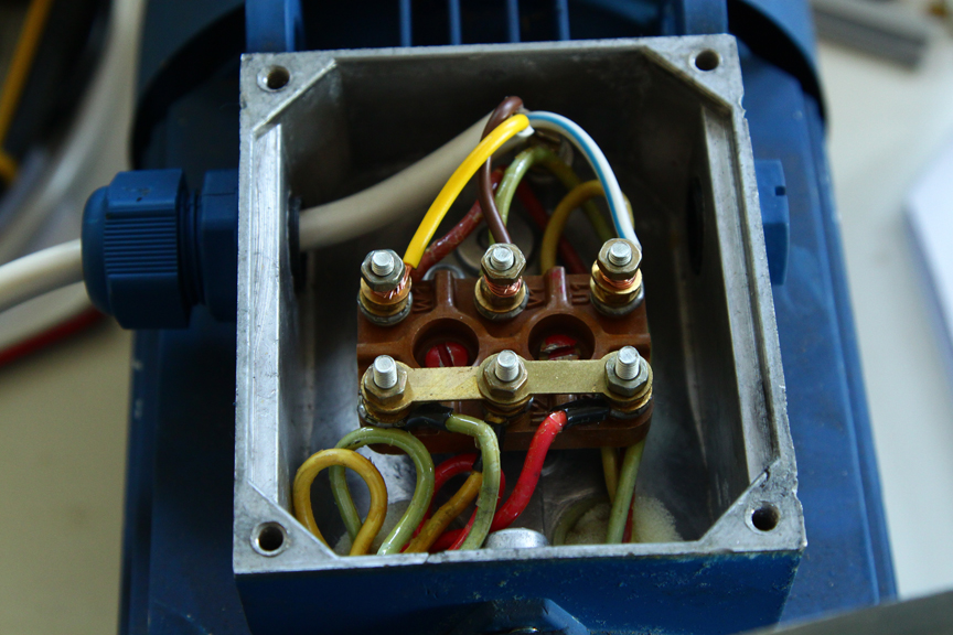
The conclusions from the windings of all three phases are located in a special box on the motor housing. It is called barno, in it the conclusions of the windings are connected to each other. Depending on the supply voltage and the technical data of the motor, the outputs are combined either into a star or a delta.
The rotor winding of any asynchronous electric motor is similar to a "squirrel cage", as it is called. It is made in the form of a series of conductive aluminum rods dispersed over the outer surface of the rotor. The ends of the rods are closed, so such a rotor is called squirrel-cage.
The winding, like the stator winding, is located inside the magnetic circuit, also made of insulated metal plates.

The principle of operation of an asynchronous electric motor
When the supply voltage is connected to the stator, current flows through the turns of the winding. It creates a magnetic field inside. Since the current is alternating, the field changes in accordance with the shape of the supply voltage. The location of the windings in space is made in such a way that the field inside it turns out to be rotating.
In the rotor winding, the rotating field induces an EMF. And since the turns of the winding are short-circuited, then a current appears in them. It interacts with the stator field, this leads to the appearance of rotation of the motor shaft.
The electric motor is called asynchronous because the stator field and the rotor rotate at different speeds. This speed difference is called slip (S). 
where:
n is the frequency of the magnetic field;
nr is the rotor speed.
To regulate the speed of the shaft over a wide range, asynchronous electric motors are made with a phase rotor. Windings displaced in space are wound on such a rotor, the same as on the stator. The ends from them are brought out to the rings, with the help of a brush apparatus, resistors are connected to them. The greater the resistance to connect to the phase rotor, the lower will be the speed of its rotation.
Asynchronous generator
And what will happen if the rotor of an asynchronous electric motor rotates? Will it be able to generate electricity, and how to make a generator from an induction motor?
It turns out that this is possible. In order for voltage to appear on the stator winding, it is initially necessary to create a rotating magnetic field. It appears due to the residual magnetization of the rotor of the electric machine. In the future, when the load current appears, the strength of the magnetic field of the rotor reaches the required value and stabilizes.
To facilitate the process of the appearance of voltage at the output, a capacitor bank is used, which is connected to the stator of the asynchronous generator at the time of start (capacitor excitation).
But the parameter inherent in an asynchronous electric motor remains unchanged: the amount of slip. Because of it, the frequency of the output voltage of the asynchronous generator will be lower than the shaft speed.
By the way, the shaft of the asynchronous generator must be rotated at such a speed that the nominal rotational speed of the stator field of the electric motor is reached. To do this, you need to find out the speed of rotation of the shaft from the plate located on the housing. By rounding its value to the nearest whole number, the rotation speed for the rotor of the electric motor converted into a generator is obtained. 
For example, for an electric motor, the plate of which is shown in the photo, the shaft rotation speed is 950 rpm. This means that the speed of rotation of the shaft should be 1000 rpm.
Why is an asynchronous generator worse than a synchronous one?
How good will a homemade generator from an induction motor be? How will it differ from a synchronous generator?
To answer these questions, we briefly recall the principle of operation of a synchronous generator. A direct current is supplied to the rotor winding through slip rings, the value of which is adjustable. The rotating field of the rotor creates an EMF in the stator winding. To obtain the required generation voltage, the automatic excitation control system will change the current in the rotor. Since the voltage at the generator output is monitored by automation, as a result of a continuous regulation process, the voltage always remains unchanged and does not depend on the magnitude of the load current.
To start and operate synchronous generators, independent power sources (batteries) are used. Therefore, the start of its operation does not depend either on the appearance of the load current at the output, or on the achievement of the required rotation speed. Only the frequency of the output voltage depends on the rotation speed.
But even when receiving the excitation current from the generator voltage, all of the above remains true.
The synchronous generator has one more feature: it is able to generate not only active, but also reactive power. This is very important when powering electric motors, transformers and other units that consume it. The lack of reactive power in the network leads to an increase in heating losses of conductors, windings of electrical machines, a decrease in the voltage at consumers relative to the generated value.
To excite an asynchronous generator, the residual magnetization of its rotor is used, which in itself is a random value. It is not possible to regulate the parameters that affect the value of its output voltage during operation.
In addition, an asynchronous generator does not generate, but consumes reactive power. It is necessary for him to create an excitation current in the rotor. Think about capacitor excitation: by connecting a bank of capacitors at start-up, the reactive power required by the generator to start working is created.
As a result, the voltage at the output of the asynchronous generator is not stable and varies depending on the nature of the load. When connected to it a large number reactive power consumers, the stator winding may overheat, which will affect the life of its insulation.
Therefore, the use of an asynchronous generator is limited. It can operate in conditions close to "greenhouse" ones: no overloads, inrush load currents, powerful reagent consumers. And at the same time, the power receivers connected to it should not be critical to changes in the magnitude and frequency of the supply voltage.
The perfect place for the use of an asynchronous generator are alternative energy systems powered by water or wind energy. In these devices, the generator does not supply the consumer directly, but charges the battery. From it already, through a DC-to-AC converter, the load is powered.
Therefore, if you need to assemble a windmill or a small hydroelectric power plant, the asynchronous generator is the best way out. Its main and only advantage works here - simplicity of design. The absence of rings on the rotor and the brush apparatus leads to the fact that during operation it does not need to be constantly maintained: clean the rings, change the brushes, remove graphite dust from them. Indeed, in order to make a wind generator from an asynchronous motor with your own hands, the generator shaft must be directly connected to the windmill blades. This means that the structure will be on high altitude. It's hard to get her out of there.
Magnetic generator
Why does a magnetic field need to be created with an electric current? After all, there are powerful sources of it - neodymium magnets.
To convert an induction motor into a generator, cylindrical neodymium magnets will be required, which will be installed in place of the standard conductors of the rotor winding. First you need to calculate the required number of magnets. To do this, remove the rotor from the engine being converted into a generator. It clearly shows the places where the winding of the "squirrel wheel" is laid. The dimensions (diameter) of the magnets are chosen so that when installed strictly in the center of the conductors of the short-circuited winding, they do not come into contact with the magnets of the next row. Between the rows there should be a gap not less than the diameter of the magnet used.
Having decided on the diameter, they calculate how many magnets will fit along the length of the winding conductor from one edge of the rotor to the other. At the same time, a gap of at least one to two millimeters is left between them. By multiplying the number of magnets in a row by the number of rows (rotor winding conductors), the required number is obtained. The height of the magnets should not be chosen very high.
To install magnets on the rotor of an asynchronous electric motor, it will need to be modified: remove a layer of metal on a lathe to a depth corresponding to the height of the magnet. In this case, the rotor must be carefully centered in the machine so as not to bring down its balance. Otherwise, he will have a shift in the center of mass, which will lead to a beating in work.
Then proceed to install the magnets on the surface of the rotor. Glue is used for fixation. Any magnet has two poles, conventionally called north and south. Within one row, the poles located away from the rotor must be the same. In order not to make a mistake in the installation, the magnets are first linked together in a garland. They will interlock in a strictly defined way, since they are attracted to each other only by opposite poles. Now it remains only to mark the poles of the same name with a marker.
In each subsequent row, the pole located outside changes. That is, if you laid out a row of magnets with a pole marked with a marker, located outside of the rotor, then the next one is laid out with magnets turned the other way around. And so on.
After gluing the magnets, they need to be fixed with epoxy. To do this, a template is made around the resulting structure made of cardboard or thick paper, into which the resin is poured. The paper is wrapped around the rotor, wrapped with tape or electrical tape. One of the end parts is covered with plasticine or also sealed. Then the rotor is installed vertically and epoxy resin is poured into the cavity between the paper and the metal. After it hardens, the fixtures are removed.
Now again we clamp the rotor into the lathe, center it, and grind the surface filled with epoxy. This is not necessary for aesthetic reasons, but to minimize the impact of possible unbalance due to additional parts installed on the rotor.
Grinding is done first with coarse-grained sandpaper. It is mounted on a wooden block, which is then evenly moved along a rotating surface. Then you can apply sandpaper with a finer grit.
Now the finished rotor can be inserted back into the stator and the resulting design can be tested. It can be successfully used by those who want to make, for example, a wind generator from an asynchronous motor. There is only one drawback: the cost of neodymium magnets is very high. Therefore, before you start to remake the rotor and spend money on spare parts, you should calculate which option is more cost-effective: make a generator from an induction motor or purchase a ready-made one.