To ensure the visibility of topographic materials and understanding the content of plans and maps, a special system of graphic designation of terrain objects, which is called conventional signs, has been developed. Conventional signs subdivided into areal, linear, off-scale, explanatory and special.
Areal (contour or scale) signs are used to fill in the contours of natural and agricultural lands, the length and width of which is expressed on the scale of the map. The boundaries of the contours are shown with a dotted line, inside which a conventional sign is depicted, resembling an object in a given area. For example, a forest is represented by circles, sands by dots, etc.
Linear and conventional signs show objects of a linear nature (roads, rivers, power lines, etc.), the length of which is expressed, but the width is not expressed on the scale of the map. Linear signs have various numerical characteristics that complement the information about the subject. For example, a highway shows the width of the carriageway and the total width of the road.
Out-of-scale conventional signs serve to depict objects whose dimensions are not expressed on the map scale (bridges, wells, kilometer posts, etc.).
Explanatory symbols are signatures that give the characteristics and names of objects, for example, the length and width of bridges, the type of forest plantations, etc. These signs are affixed to the main areal, linear and off-scale symbols.
Special symbols are used by the relevant departments when compiling special maps and plans for this industry, for example, communication pipelines (heating mains, water supply, etc.).
In addition to conventional signs, for greater clarity, images of various elements of topographic maps are used color:
For rivers, lakes, canals, wetlands - blue;
For forests and gardens - green;
Highways - red;
Railroads and the rest of the situation is black;
The contours characterizing the terrain are shown in brown.
In addition to colors, the type of font, the thickness of the letters, their height and inclination in the designation are also used. Conventional signs for different scales are summarized in special collections published by geodesy and cartography services. They are obligatory for all departments and organizations involved in drawing up plans, maps, and topographic surveys of the area.
Knowledge of conventional signs is necessary in order to understand the content of topographic materials, to be able to “read” them and to obtain the necessary information. For a better acquaintance with conventional signs on educational topographic maps, their main samples are given.
3.6 Terrain relief and its representation on plans and maps.
Contours and their properties. Ways to build contour lines
by marks of points
relief called a set of irregularities of the earth's surface. Knowledge of the terrain is necessary in the design and construction of railways and roads, drainage and irrigation systems, industrial enterprises, etc. There are several ways to depict the relief on topographic maps and plans. The oldest method is the image of the relief of the strokes, which are applied to the map on a special scale. The relief of the area can also be depicted under the signatures and marks of a number of dots or washes in paint and different tones. However, it turned out to be the best way to depict the relief of the horizon - l and in combination with some conventional signs and signatures of marks of characteristic points. A horizontal line is a line connecting points on the earth's surface with the same height.
To correctly depict the relief, you need to know its basic forms. There are five main landforms (figure 3.5):
Elevation (Figure 3.5, a);
Basin (Figure 3.5, b);
Ridge (Figure 3.5, c);
Hollow (Figure 3.5, d);
Saddle (Figure 3.5, e).
Figure 3.5 shows these landforms in section. Consider the essence of the image of the relief by contour lines. Figure 3.5, a shows a hill (hill, mountain), the highest point of which is called the top, the bottom - the sole, and the side surfaces - slopes. To depict a hill with horizontal lines, let us imagine that this hill is crossed by a series of equally spaced planes parallel to the main level surface. The lines of intersection of these planes of the earth's surface will be contour lines. Projecting them with sheer lines onto a plane, we get an image of a hill on it.
For clarity, some horizontal lines are signed, in addition, they put berghash lines showing the direction of the slope of the area.
The distance between two adjacent cutting planes is called the height of the relief section h. On maps and plans, the height of the relief section is characterized by the difference in the heights of two adjacent horizontals. For example, in Figure 3.5, and the height of the relief section is h = 5 m.
The distance between contour lines on a plan or map is called the laying. In Figure 3.5, a laying d = AC. The relationship between the height of the relief section h, the laying d, the angle of inclination υ, the slope i and the terrain line AB can be obtained from the triangle ABC (Figure 3.5, a):
i = h / d = tg υ. (3.6)
The slope and angle of the terrain line are the main characteristics of the steepness of the slopes. The greater the angle of inclination, the steeper the slope of the terrain. From formula (3.6) it follows that the smaller the laying d or the more horizontals on the plan, the steeper the slope of the terrain.
The contour lines of the basin, hollow, ridge and saddle are shown in Figure 3.5. Hollow (depression) - a closed depression of the surface (see Figure 3.5, b). The lowest part of the depression is called the bottom, the side surfaces are called the slopes, and the line of confluence with the surrounding area is called the edge.
|
|
|
|
|
|
|
|
|
 b)
b) V)
V) G)
G)
Figure 3.5 - Basic landforms
Ridge - a hill elongated in one direction with two slopes (see Figure 3.5, c). The line of meeting of the slopes in the upper part is called the watershed (watershed line).
Hollow - a depression elongated in one direction with two slopes (Figure 3.5 d). The line of meeting of the slopes in their lower part is called the weir or thalweg (weir line).
Saddle - a depression between two hills (see Figure 3.5 e). The lowest point between the hills is called the pass.
Bergstrokes on maps and plans are usually shown along watershed and spillway lines. Signatures on horizontal lines make the base of the number show the direction of the slope. Horizontal lines are drawn in brown. Every tenth or fifth of them is drawn with a thickened line.
Their properties follow from the essence of contour lines:
The horizontal is a closed curved line, all points on which have the same height, a multiple of the height of the relief section;
Horizontals on the plan cannot fork and break off; if the horizontal does not close within the plan, it closes beyond its limit;
Horizontals should not intersect with each other, since they are obtained by crossing the earth's surface with planes lying at different heights;
The more often the horizontals on the plan, the greater the slope of the terrain, or the smaller the laying, the steeper the slope;
Watershed and spillway lines and directions of maximum horizontal slope cross at right angles.
The height of the relief section is set depending on the scale of the plan and the nature of the terrain so that the contours do not merge with each other. In the Republic of Belarus, the following heights of the relief section are accepted at the survey scale:
|
1:500 - h = 0.25; 0.5 m; 1:1000 - h = 0.25; 0.5; 1m; 1:2000 - h = 0.5; 1; 2 m; |
1:5000 - h = 0.5; 1; 2; 5 m; 1:10000 - h = 1; 2.5; 5 m |
For a more complete image and ease of reading the relief on maps and plans, marks of characteristic points of the relief (tops of hills, the bottom of basins, passes, etc.) are signed. For example, in Figure 3.5, b, the mark of the bottom of the basin is 98.7 m.
Methods for constructing contour lines by point marks. To draw contour lines on a plan, you need to plot characteristic points taken on the ground and write out their heights. Those points between which the earth's surface has no fractures, i.e., has a constant slope, connect with lines. Further, on each line, by interpolation, the points of intersection of its contour lines are found and the heights of these contour lines are noted. Having then connected points with the same heights with smooth curved lines, an image of the terrain on the plan is obtained. Thus, the task of constructing contour lines on a plan basically boils down to the ability to find projections of the points of intersection of lines by contour lines, the marks of the ends of which are known, while the height of the relief section must already be established. This task is called the interpolation of contour lines, i.e., finding intermediate values for the heights of contour lines using point marks. Interpolation can be done analytically or graphically.
analytical way. According to the known heights of points A and B and the distance d between them (Figure 3.6, a), it is necessary to find the distances d 1 and d 2 from point A to points M 0 and N 0 with marks H m and H N equal to the marks of contour lines.

Figure 3.6 - Analytical method of interpolation
From the similarity of triangles ABB O, AMM O and ANN O we find:
d 1 \u003d dh 1 / h; d 2 \u003d dh 2 / h,
where h \u003d H B - H A; h 1 \u003d H M - H A; h 2 \u003d H N - H A.
On the plan, the segments d 1 and d 2 are laid aside and the points M O and N O are obtained, at which their marks are signed. It should be noted that contour lines are interpolated only along lines with a uniform slope. Figure 3.6, b shows the case of incorrect interpolation between points A and C with an uneven slope of the terrain. As can be seen from the figure, instead of the actual position of point B, point B " will be obtained and, accordingly, instead of H B, the wrong height H B " will be obtained.
Graphic way. Interpolation in this way is performed using graph paper or transparent paper. If there is millimeter paper, it is applied to the plan line AB. According to the marks of the ends AB, a profile of this line is built. Projecting then on the plan line of the point of change  sections of the profile line with graph paper lines taken as secant planes receive the desired points M and N. In the presence of transparent paper (wax, tracing paper), a number of equally spaced parallel lines are preliminarily applied to it, which are given marks of secant planes. The wax is applied to the plan so that the end points of the plan line take a position corresponding to their marks between the wax lines (Figure 3.7). Further, the points of intersection of the plan line with the lines of waxing are pierced onto the plan. These will be the desired points on the plan.
Conventional signs of topographic maps
Tikhonova L.Ya. geography teacher, MBOU "Lyceum No. 3", Prokhladny, KBR


Do you know the symbols?

Read the letter
Hello mother!
We went hiking. We left early in the morning
out, went on up,
turned west and approached
.To the right of us was,
. Then, past along
by we returned to.

The glorious hero Alyosha Popovich lived in Rus',
and he only knew how to lie on the stove, and with Tugarin
Let's fight the snake. He went once gold
free the people from the paws of the Tugarins.
His path lay through birch forest , past the rotten
swamps through which path was. I went
Alyosha into the very thicket of the forest and sees the picturesque lake ,
and next to him forester's house . He asks the forester
how to get him river , where is the Tugarin army
located. And the old man answers him, the way is long
you have to. First you go to dirt road ,
turn into Pine forest . There you will see golodets ,
boldly go from him to spring , at the spring
have a deep ravine , you will cross it and you will see meadow ,
standing on that meadow lonely tree .
If you approach him, Tugarin himself will appear.
Write the story in symbols
http://aida.ucoz.ru

Determine the direction

Measure the distance using the scale in fig. 39
in 1 cm 100 m
- Determine the scale of the plan.
- Measure the distance from the birch to the barn with a ruler.
- Calculate the distance using the scale.
- Determine the distance from the birch to the point 162.3 m; to the lake; to the wooden bridge.
0.9 cm
0.9 cm x 100 m = 90 m

Draw a plan of the area
An observer stands in the center of the area in the meadow. He sees:
- North, 300 m, school
- East, 250 m, bushes
- N-W, 400 m, orchard
- To the south, 150 m, the lake, the eastern shore is swampy
- South-west, 200 m, bush
- On the s-v, 450 m, mixed forest
- 3, 200 m, light forest
- South-east, 100 m, well
M: in 1cm 100m
Plan from one point is called polar
http://aida.ucoz.ru

Draw a route plan for the area (M 1: 10000m)
The guys went from school (v. 1) on an excursion (the school is located in the northwest area)
v.1 → v.2 - on c. 800 m along the path through the orchard,
v.2 - a well on the bank of the river. Belka, the river flows from the south. us.
v.2→v.3 - 500 m against the river along the path through the bushes,
v.3 - spring,
t.3 → t.4 - on the s-w. on a dirt road through the field 400 m.
v.4 - a windmill, to the south of v.4 we saw a lake, the eastern shore of which is swampy,
t.4→t.5 - to the south-west. 400 m along the path through the meadow to the birch (v. 5),
v.5→v.1 – back to school on a dirt road through woodlands
http://aida.ucoz.ru

draw a sign

draw a sign
windmill

draw a sign

draw a sign
rare forest

draw a sign
free standing tree
Symbols on a map or plan are a kind of their alphabet, by which they can be read, find out the nature of the area, the presence of certain objects, and evaluate the landscape. As a rule, conventional signs on the map convey common features with geographical objects that exist in reality. The ability to decipher cartographic symbols is indispensable when making hiking trips, especially to distant and unfamiliar areas.
All objects marked on the plan can be measured on the scale of the map to represent their actual size. Thus, conventional signs on a topographic map are its “legend”, their decoding for the purpose of further orientation in the area. Homogeneous objects are indicated by the same color or stroke.
All the outlines of objects located on the map, according to the method of graphic representation, are divided into several types:
- Areal
- Linear
- Point
The first type consists of objects that occupy a large area on a topographic map, which are expressed by areas enclosed in boundaries in accordance with the scale of the map. These are objects such as lakes, forests, swamps, fields.
Linear designations are outlines in the form of lines, they can be seen on the scale of the map along the length of the object. These are rivers, railways or roads, power lines, clearings, streams, etc.
Dot outlines (off-scale) denote objects of small size that cannot be expressed on the scale of the map. It can be both individual cities and trees, wells, pipes and other small single objects.
Symbols are applied in order to have the most complete picture of the indicated area, but this does not mean that absolutely all the smallest details of a real individual district or city have been identified. The plan indicates only those objects that are of great importance for the national economy, the Ministry of Emergency Situations, as well as military personnel.
Types of symbols on maps
 Symbols used on military maps
 To recognize the signs of the map, you need to be able to decipher them. Conditional symbols are divided into scale, off-scale and explanatory.
- Scale symbols indicate local objects that can be expressed in terms of their size on the scale of a topographic map. Their graphic designation appears as a small dotted line or thin line. The area inside the border is filled with conditional icons that correspond to the presence of real objects in this area. Scale signs on a map or plan can be used to measure the area and dimensions of a real topographic object, as well as its outlines.
- Out-of-scale symbols indicate objects that cannot be displayed on the scale of the plan, the size of which cannot be judged. These are some separate buildings, wells, towers, pipes, kilometer posts and so on. Out-of-scale symbols do not indicate the dimensions of an object located on the plan, so it is difficult to determine the actual width, length of a pipe, elevator, or a free-standing tree. The purpose of off-scale markings is to accurately indicate a particular object, which is always important when navigating when traveling in unfamiliar terrain. The exact indication of the location of the indicated objects is carried out by the main point of the symbol: it can be the center or the lower middle point of the figure, the top of the right angle, the lower center of the figure, the axis of the symbol.
- Explanatory signs serve to disclose information about scale and off-scale designations. They give an additional characteristic of objects located on a plan or map, for example, indicating the direction of the river flow with arrows, designating the type of forest with special signs, the carrying capacity of the bridge, the nature of the road surface, the thickness and height of the trees in the forest.

In addition, topographic plans place other designations on themselves that serve as an additional characteristic for some of the indicated objects:
- Signatures
Some signatures are used in full, others are abbreviated. The names of settlements, the names of rivers, lakes are fully deciphered. Abbreviated labels are used to indicate more detailed characteristics of some objects.
- Numerical symbols
They are used to indicate the width and length of rivers, roads and railways, transmission lines, the height of points above sea level, the depth of fords, etc. The standard designation of the map scale is always the same and depends only on the size of this scale (for example, 1:1000, 1:100, 1:25000, etc.).
In order to make it as easy as possible to navigate on a map or plan, the symbols are indicated by different colors. To distinguish even the smallest objects, more than twenty different shades are used, from intensely colored areas to less bright ones. To make the map easy to read, at the bottom of it is a table with a decoding of color designations. So, usually water bodies are indicated in blue, blue, turquoise; forest objects in green; terrain - brown; city blocks and small settlements - gray-olive; highways and highways in orange; state borders in purple, neutral area in black. Moreover, blocks with fire-resistant buildings and structures are marked in orange, and blocks with non-fire-resistant structures and improved dirt roads - in yellow.

The unified system of symbols for maps and terrain plans is based on the following provisions:
- Each graphic sign always corresponds to a certain type or phenomenon.
- Each sign has its own clear pattern.
- If the map and plan differ in scale, the objects will not differ in their designation. The difference will only be in their size.
- Drawings of real terrain objects usually indicate an associative connection with it, therefore they reproduce the profile or appearance of these objects.
To establish an associative connection between a sign and an object, there are 10 types of formation of compositions:

Topic 8. CARTOGRAPHIC SYMBOLS
8.1. CLASSIFICATION OF CONVENTIONAL SIGNS
On maps and plans, the image of terrain objects (situations) is presented in cartographic symbols. Cartographic symbols
- a system of symbolic graphic designations used to depict various objects and phenomena on maps, their qualitative and quantitative characteristics. Symbols are sometimes also called "map legend".
For ease of reading and memorization, many conventional signs have styles that resemble the view of the local objects depicted by them from above or from the side. For example, conventional signs of factories, oil rigs, isolated trees, and bridges are similar in shape to the appearance of the listed local objects.
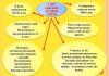
Cartographic symbols are usually divided into large-scale (contour), off-scale and explanatory (Fig. 8.1). In some textbooks, linear conventional signs are singled out as a separate group.
Rice. 8.1. Symbol types
large-scale
(contour) signs are called conventional signs used to fill in the areas of objects expressed on the scale of a plan or map. According to a plan or map, it is possible to determine with the help of such a sign not only the location of the object, but its size and shape.
The boundaries of areal objects on the plan can be depicted with solid lines of different colors: black (buildings and structures, fences, roads, etc.), blue (reservoirs, rivers, lakes), brown (natural landforms), light pink (streets and areas in settlements), etc. The dotted line is used for the boundaries of agricultural and natural lands of the area, the boundaries of embankments and cuts near roads. The boundaries of clearings, tunnels and some structures are indicated by a simple dotted line. The fill characters inside the outline are arranged in a specific order.
Linear symbols(a kind of scale conventional signs) are used when depicting objects of a linear nature - roads, power lines, borders, etc. The location and planned outline of the axis of a linear object are depicted accurately on the map, but their width is greatly exaggerated. For example, the symbol of a highway on maps at a scale of 1:100,000 exaggerates its width by 8 to 10 times.
If an object on a plan (map) cannot be expressed by a scale symbol due to its smallness, then off-scale
symbol, for example, a landmark, a separately growing tree, a kilometer post, etc. The exact position of an object on the ground is shown main point
off-scale symbol. The main point is:
- for signs of a symmetrical shape - in the center of the figure (Fig. 8.2);
- for signs with a wide base - in the middle of the base (Fig. 8.3);
- for signs that have a base in the form of a right angle - at the top of the corner (Fig. 8.4);
- for signs that are a combination of several figures - in the center of the lower figure (Fig. 8.5).

Rice. 8.2. Symmetrical signs
1 - points of the geodetic network; 2 - points of the survey network, fixed on the ground by centers; 3 - astronomical points; 4 - churches; 5 - plants, factories and mills without pipes; 6 - power plants; 7 - water mills and sawmills; 8 - fuel depots and gas tanks; 9 - mines and adits operating; 10 - oil and gas wells without rigs

Rice. 8.3. Signs with a wide base
1 - factory and factory pipes; 2 - waste heaps; 3 - telegraph and radiotelegraph offices and departments, telephone exchanges; 4 - meteorological stations; 5 - semaphores and traffic lights; 6 - monuments, monuments, mass graves, tours and stone pillars over 1 m high; 7 - Buddhist monasteries; 8 - separately lying stones

Rice. 8.4. Signs having a base in the form of a right angle
1 - wind turbines; 2 - gas stations and filling stations; 3 - windmills; 4 - permanent river signaling signs;
5 - free-standing deciduous trees; 6 - free-standing coniferous trees

Rice. 8.5. Signs that are a combination of several figures
1 - plants, factories and mills with pipes; 2 - transformer boxes; 3 - radio stations and television centers; 4 - oil and gas rigs; 5 - tower-type structures; 6 - chapels; 7 - mosques; 8 - radio masts and television masts; 9 - kilns for burning lime and charcoal; 10 - mazars, suborgans (religious buildings)
Objects, expressed by off-scale conventional signs, serve as good landmarks on the ground.
Explanatory symbols
(Fig. 8.6, 8.7) are used in combination with large-scale and off-scale; they serve to additionally characterize local objects and their varieties. For example, the image of a coniferous or deciduous tree in combination with a symbol of a forest shows the dominant tree species in it, an arrow on a river indicates the direction of its flow, transverse strokes on a symbol of a railway show the number of tracks.

Rice. 8.6. Explanatory conventional signs of the bridge, highway, river

Rice. 8.7. Stand characteristics
In the numerator of the fraction - the average height of the trees in meters, in the denominator - the average thickness of the trunks, to the right of the fraction - the average distance between the trees
The maps contain signatures of their own names of settlements, rivers, lakes, mountains, forests and other objects, as well as explanatory signatures in the form of letters and numbers. They provide additional information about the quantitative and qualitative characteristics of local objects and relief. Letter explanatory signatures are most often given in abbreviated form according to the established list of conditional abbreviations.
For a more visual depiction of the terrain on maps, each group of conventional signs relating to the same type of terrain elements (vegetation cover, hydrography, relief, etc.) is printed with ink of a certain color.
8.2. CONVENTIONAL SIGNS OF LOCAL ITEMS
Settlements
on topographic maps at a scale of 1:25,000 - 1:100,000 they show everything (Fig. 8.8). Next to the image of the settlement, its name is signed: cities - in capital letters of a direct font, and a settlement of a rural type - in lowercase letters of a smaller font. Under the name of a rural-type settlement, the number of houses (if known) is indicated, and if there are district and village councils in them, their abbreviated signature (PC, CC).
The names of urban and suburban settlements are printed on the maps in italic capital letters. When depicting settlements on maps, their external outlines and the nature of the layout are preserved, the main and through passages, industrial enterprises, prominent buildings and other buildings that are important as landmarks are distinguished.
Wide streets and squares depicted on the scale of the map are shown with large-scale conventional signs in accordance with their actual size and configuration, other streets are shown with conventional off-scale signs, the main (main) streets are highlighted on the map with a wider gap.

Rice. 8.8. Settlements
Settlements are depicted in the most detail on maps at a scale of 1:25,000 and 1:50,000. Quarters with predominantly fire-resistant and non-fire-resistant buildings are painted over with the appropriate color. Buildings located on the outskirts of settlements are shown, as a rule, all.
On a map of scale 1: 100,000, the image of all main streets, industrial facilities and the most important objects of landmark value is mainly preserved. Separate buildings within blocks are shown only in settlements with very sparse buildings, for example, in dacha-type settlements.
When depicting all other settlements, the buildings are combined into quarters and filled with black paint, the fire resistance of buildings on the map 1:100,000 is not highlighted.
Selected local items
Landmarks that matter are mapped most accurately. Such local items include various towers and towers, mines and adits, wind turbines, churches and separately located buildings, radio masts, monuments, individual trees, barrows, remnant rocks, etc. All of them, as a rule, are depicted on maps conventional off-scale signs, and some are accompanied by abbreviated explanatory captions. For example, the signature check ug. with the sign of the mine means that the mine is hard coal.

Rice. 8.9. Selected local items
Road network
on topographic maps is depicted in full and in detail. Railways show everything on maps and are divided according to the number of tracks (one-, two- and three-track), gauge (normal and narrow gauge) and condition (operating, under construction and dismantled). Electrified railways are distinguished by special conventional signs. The number of tracks is indicated by dashes perpendicular to the axis of the conventional sign of the road: three dashes - three-track, two - double-track, one - single-track.
On the railways, stations, sidings, platforms, depots, wayposts and booths, embankments, excavations, bridges, tunnels, semaphores and other structures are shown. Own names of the station (sidings, platforms) are signed next to their conventional signs. If the station is located in a settlement or near it and has the same name as it, then its signature is not given, but the name of this settlement is underlined. The black rectangle inside the station symbol indicates the location of the station relative to the tracks: if the rectangle is in the middle, then the tracks pass on both sides of the station.

Rice. 8.10. Railway stations and facilities
Conventional signs of platforms, checkpoints, booths and tunnels are accompanied by the corresponding abbreviated signatures ( sq., bl. n., B, tun.). Next to the conventional sign of the tunnel, in addition, its numerical characteristic is placed in the form of a fraction, in the numerator of which the height and width are indicated, and in the denominator - the length of the tunnel in meters.
Highway
And ground
roads
when depicted on maps, they are divided into paved and unpaved roads. Paved roads include freeways, improved highways, highways, and improved dirt roads. Topographic maps show all paved roads available in the area. The width and material of the pavement of motorways and highways are signed directly on their conventional signs. For example, on the highway the signature 8(12)A means: 8
- width of the covered part of the road in meters; 12
- width of the road from ditch to ditch; A- coating material (asphalt). On improved dirt roads, only the width of the road from ditch to ditch is usually given. Freeways, improved highways, and highways are highlighted in orange on maps, improved dirt roads - in yellow or orange.

Figure 8.11. Highways and dirt roads
Topographic maps show unsurfaced (country), field and forest roads, caravan routes, trails and winter roads. In the presence of a dense network of roads of a higher class, some secondary roads (field, forest, dirt) on maps at a scale of 1:200,000, 1:100,000, and sometimes 1:50,000 may not be shown.
Sections of dirt roads passing through wetlands, lined with bundles of brushwood (fascines) on wooden beds and then covered with a layer of earth or sand, are called fascinated road sections. If on such sections of the road, instead of fascines, a flooring of logs (poles) or simply an embankment of earth (stones) is made, then they are called gats and rowings, respectively. Fashin sections of roads, gati and rowing on the maps are indicated by dashes perpendicular to the conventional sign of the road.
On highways and dirt roads, bridges, pipes, embankments, excavations, tree plantings, kilometer posts and passes (in mountainous areas) are shown.
Bridges
they are depicted on maps with conventional signs of various designs depending on the material (metal, reinforced concrete, stone and wood); at the same time, two-tier, as well as drawbridges and drawbridges are distinguished. Bridges on floating supports are distinguished by a special symbol. Next to the conventional signs of bridges with a length of 3 m or more, and located on roads (except for motorways and improved highways), they sign their numerical characteristics in the form of a fraction, the numerator of which indicates the length and width of the bridge in meters, and the denominator - the carrying capacity in tons. Before the fraction indicate the material from which the bridge is built, as well as the height of the bridge above the water level in meters (on navigable rivers). For example, the signature next to the symbol of the bridge (Fig. 8.12) means that the bridge is stone (construction material), in the numerator - the length and width of the roadway in meters, in the denominator - the carrying capacity in tons.

Rice. 8.12. Overpass over the railroad
When designating bridges on freeways and improved highways, only their length and width are given. The characteristics of bridges with a length of less than 3 m are not given.
8.3. HYDROGRAPHY (WATER BODIES)
Topographic maps show the coastal part of the seas, lakes, rivers, canals (ditches), streams, wells, springs, ponds and other bodies of water. Their names are signed next to them. The larger the scale of the map, the more detailed the water bodies are depicted.
Lakes, ponds and other bodies of water are shown on maps if their area is 1 mm2 or more on the scale of the map. Reservoirs of smaller sizes are shown only in arid and desert regions, as well as in cases where they have the value of reliable landmarks.

Rice. 8.13. Hydrography
Rivers, streams, canals and main ditches topographic maps show everything. At the same time, it was found that on maps of scales 1:25,000 and 1:50,000, rivers up to 5 m wide, and on maps of a scale of 1:100,000 - up to 10 m, are indicated by one line, wider rivers - by two lines. Channels and ditches with a width of 3 m or more are depicted with two lines, with a width of less than 3 m - with one.
The width and depth of the rivers (channels) in meters are signed as a fraction: in the numerator - the width, in the denominator - the depth and nature of the bottom soil. Such signatures are placed in several places along the river (channel).
River speed (m/s), depicted by two lines, indicate in the middle of the arrow showing the direction of the flow. On rivers and lakes, they also sign the height of the water level in low water in relation to sea level (marks of water edges).
On the rivers and canals they show dams, gateways, ferries (transportation), fords and give corresponding characteristics.
wells are indicated by blue circles, next to which the letter is placed TO or signature art. To. (artesian well).
Ground water pipelines show solid blue lines with dots (through 8 mm), and underground - broken lines.
To make it easier to find and select sources of water supply in the steppe and desert regions on the map, the main wells are distinguished by a larger symbol. In addition, if there is data to the left of the symbol of the well, an explanatory signature of the ground level mark is given, to the right - the depth of the well in meters and the filling rate in liters per hour.
8.4. SOIL AND VEGETATION COVER
Soil
-vegetable
cover
are usually depicted on maps with large-scale symbols. These include conventional signs of forests, shrubs, gardens, parks, meadows, marshes and salt marshes, as well as conventional signs depicting the nature of the soil cover: sands, rocky surface, pebbles, etc. When designating the soil and vegetation cover, a combination of conditional signs. For example, in order to show a swampy meadow with bushes, the contour is the area occupied by the meadow, inside which the symbols of the swamp, meadow and bushes are placed.
The contours of areas covered with forests, shrubs, as well as the contours of swamps, meadows are indicated on the maps by a dotted line. If a linear local object (ditch, fence, road) serves as the boundary of a forest, garden or other area, then in this case the symbol of a linear local object replaces the dotted line.
Forest, shrubs. The forest area inside the contour is painted over with green paint. The tree species is shown with a deciduous, coniferous tree icon, or a combination of both when the forest is mixed. If there is data on the height, thickness of trees and density of the forest, its characteristics are indicated with explanatory signatures and numbers. For example, the signature indicates that coniferous trees (pine) predominate in this forest, their average height is 25 m, the average thickness is 30 cm, the average distance between tree trunks is 4 m. When depicted on the map, clearings indicate their width in meters.

Rice. 8.14. Forests

Rice. 8.15. shrubs
swamps are depicted on the maps with blue horizontal shading with their division according to the degree of passability on foot into passable (broken shading), difficult to pass and impassable (solid shading). Passable swamps are considered to be no more than 0.6 m deep; their depth on maps is usually not signed.

Rice. 8.16. swamps
The depth of difficult and impenetrable swamps is signed next to the vertical arrow indicating the location of the measurement. Impenetrable and impassable swamps are shown on the maps with the same symbol.
Salt marshes on the maps they are shown by vertical shading in blue with their division into passable (broken shading) and impassable (solid shading).
On topographic maps, as their scale decreases, homogeneous topographic symbols are combined into groups, the latter - into one generalized symbol, etc. In general, the system of these designations can be represented as a truncated pyramid, at the base of which are signs for topographic plans at a scale of 1:500, and at the top - for survey topographic maps at a scale of 1:1,000,000.
8.5. COLORS OF TOPOGRAPHIC SYMBOLS
Colors
topographic symbols are the same for maps of all scales. Line marks of lands and their contours, buildings, structures, local objects, strongholds and boundaries are printed when publishing black color, relief elements - brown; reservoirs, streams, swamps and glaciers - blue(mirror of water - light blue); areas of tree and shrub vegetation - green(dwarf forests, elfins, shrubs, vineyards in light green), fire-resistant neighborhoods and highways in orange, non-fire-resistant neighborhoods and improved dirt roads in yellow.
Along with topographic symbols for topographic maps, conditional abbreviations of own names
political and administrative units (for example, Lugansk region - Lug.) and explanatory terms (for example, power plant - el.-st., southwestern - SW, worker's settlement - r. p.).
8.6. CARTOGRAPHIC FONTS USED ON TOPOGRAPHIC PLANS AND MAPS
A font is a graphic style of letters and numbers. Fonts that are used on topographic pianos and maps are called cartographic.
Depending on a number of graphic features, cartographic fonts are divided into groups:
- according to the slope of the letters - straight (ordinary) and italic with slopes to the right and left;
- according to the width of the letters - narrow, normal and wide;
- by lightness - light, bold and bold;
- by the presence of undercuts.
On topographic maps and plans, two types of basic fonts are mainly used: topographic and skeleton italics (Fig. 8.17).

Rice. 8.17. Core fonts and cursive numerals
Topographic (hairline) font
T-132 is used to sign rural-type settlements. It is drawn with a line thickness of 0.1-0.15 mm, all elements of the letters are thin hair lines.
Base italic
finds application in the design of topographic maps, agricultural maps, land management pianos, etc. On topographic maps, explanatory signatures and characteristics are made in italics: astronomical points, ruins, factories, factories, stations, etc. The design of the letters has a pronounced oval shape . The thickness of all elements is the same: 0.1 - 0.2 mm.
Computational Font
or cursive letters of numbers, belongs to the group of cursive fonts. It was designed for entries in field journals and computational sheets, since in geodesy many processes of field and cameral work were associated with recording the results of instrumental measurements and their mathematical processing (see Fig. 8.17).
Modern computer technology provides a wide, almost unlimited choice of fonts of different types, sizes, patterns and slopes.
8.7. SIGNS ON TOPOGRAPHIC PLANS AND MAP
In addition to conventional signs, there are various inscriptions on topographic plans and maps. They constitute an important element of the content, explain the depicted objects, indicate their qualitative and quantitative characteristics, and serve to obtain reference information.
According to their meaning, the inscriptions are:
- own names of geographical objects (cities, rivers, lakes
and etc.); - part of a conventional sign (garden, arable land);
- conventional signs and own names at the same time (signatures of the names of cities, objects of hydrography, relief);
- explanatory captions (lake, mountain, etc.);
- explanatory text (transfer information about the distinctive features of objects, specify their nature and purpose) (Fig. 8.18).
The inscriptions on the cards are made in different fonts, differing in the pattern of letters. Up to 15 different fonts can be used on maps. The pattern of the letters of each font has elements that are unique to this font, which is based on knowledge of the features of various fonts.
Certain fonts are used for groups of related objects. For example, roman fonts are used for city names, italic fonts for names of hydrographic objects, etc. Each inscription on the map should be well read.
There are distinctive features in the arrangement of inscriptions of their own names. The names of settlements are located on the right side of the contour parallel to the northern or southern side of the map frame. This position is most desirable, but not always feasible. The names should not cover the images of other objects and fit in the map frame, so it is necessary to place the names to the left, above and below the contour of the settlement.


Rice. 8.18. Examples of inscriptions on maps
The names of areal objects are placed inside the contours, so that the signature is evenly distributed over the entire area of the object. The name of the river is placed parallel to its channel. Depending on the width of the river, the inscription is placed inside or outside the outline. It is customary to sign large rivers several times: at the source, at characteristic bends, at the confluence of rivers, etc. When one river flows into another, the inscriptions of the names are placed so that there is no doubt about the name of the rivers. Before the confluence, the main river and tributary are signed, after the confluence, the name of the main river is required.
When arranging inscriptions located not horizontally, special attention is paid to their readability. The following rule is followed: if the elongated contour along which the inscription is to be placed is located from northwest to southeast, then the inscription is placed from top to bottom; if the contour stretches from northeast to southwest, then the inscription is placed from bottom to top.
The names of the seas and large lakes are placed inside the contour of the basins along a smooth curve, in the direction of their length and symmetrically to the shores. The inscriptions of small lakes are placed as inscriptions of settlements.
The names of the mountains are placed, if possible, to the right of the top of the mountains and parallel to the southern or northern frame. The names of mountain ranges, sand formations and deserts are signed in the direction of their length.
Explanatory inscriptions are placed parallel to the north side of the frame.
Numerical characteristics are arranged depending on the nature of the information they transmit. The number of houses in rural-type settlements, elevations of the earth's surface and water lines are signed parallel to the northern or southern side of the frame. The speed of the river flow, the width of the roads and the material of their coating are located along the axis of the object.
Labels should be located in the least loaded places of the cartographic image, so that there is no doubt about which object they refer to. The inscriptions should not cross the confluence of rivers, the characteristic details of the relief, images of objects that have the value of landmarks.
Basic rules for constructing cartographic fonts: http://www.topogis.ru/oppks.html
Questions and tasks for self-control
- What are conventional signs?
- What types of symbols do you know?
- What objects are depicted on maps with large-scale symbols?
- What objects are depicted on maps with off-scale symbols?
- What is the purpose of the main point of the off-scale symbol?
- Where is the main point located on the out-of-scale symbol?
- What is the purpose of color schemes?
- What is the purpose of using explanatory labels and numbers on maps?