Scale, or contour, conditional topographic signs are used to depict local objects that, by their size, can be expressed on a map scale, that is, their dimensions (length, width, area) can be measured on a map. For example: a lake, a meadow, large gardens, quarters of settlements. The contours (outer boundaries) of such local objects are depicted on the map with solid lines or dotted lines, forming figures similar to these local objects, but only in a reduced form, that is, on a map scale. Solid lines show the contours of quarters, lakes, wide rivers, and the contours of forests, meadows, swamps - dotted lines.
Figure 31.
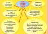
Structures and buildings, expressed on the scale of the map, are depicted by figures similar to their actual outlines on the ground and are painted over in black. Figure 31 shows several scale (a) and off-scale (b) symbols.
Off-scale symbols
Explanatory topographic signs serve to additionally characterize local objects and are used in combination with large-scale and off-scale signs. For example, a figurine of a coniferous or deciduous tree inside the outline of a forest shows the dominant tree species in it, an arrow on a river indicates the direction of its flow, etc.
In addition to signs, full and abbreviated signatures are used on the maps, as well as digital characteristics of some objects. For example, the signature "mash." with the sign of the plant means that this plant is a machine-building plant. The names of settlements, rivers, mountains, etc. are fully signed.
Numerical designations are used to indicate the number of houses in rural settlements, the height of the area above sea level, the width of the road, the characteristics of the carrying capacity and the size of the bridge, as well as the size of the trees in the forest, etc. Numerical designations related to conventional relief signs are printed in brown , width and depth of rivers in blue, everything else in black.
Let us briefly consider the main types of topographic symbols for depicting the area on the map.
Let's start with terrain. Due to the fact that observation conditions, terrain passability and its protective properties largely depend on its nature, the terrain and its elements are depicted on all topographic maps in great detail. Otherwise, we could not use the map to study and evaluate the area.
In order to clearly and fully imagine the area on the map, you must first of all be able to quickly and correctly determine on the map:
Types of irregularities of the earth's surface and their relative position;
Mutual excess and absolute heights of any points of the terrain;
The shape, steepness and length of the slopes.
On modern topographic maps, the relief is depicted by contour lines, that is, curved closed lines, the points of which are located on the ground at the same height above sea level. In order to better understand the essence of the depiction of the relief by contour lines, let us imagine an island in the form of a mountain, gradually flooded with water. Let us assume that the water level successively stops at regular intervals equal in height to h meters (Fig. 32).
Then each water level will have its own coastline in the form of a closed curved line, all points of which have the same height. These lines can also be considered as traces of a section of terrain irregularities by planes parallel to the level surface of the sea, from which heights are counted. Based on this, the distance h in height between the secant surfaces is called the height of the section.

Figure 32.
So, if all lines of equal heights are projected onto the level surface of the sea and depicted on a scale, then we will get an image of a mountain on a map in the form of a system of curved closed lines. These will be horizontal.
In order to find out whether it is a mountain or a basin, there are slope indicators - small dashes that are applied perpendicular to the horizontal lines in the direction of lowering the slope.

Figure 33.
The main (typical) landforms are shown in Figure 32.
The height of the section depends on the scale of the map and on the nature of the relief. The normal height of the section is considered to be a height equal to 0.02 of the map scale value, that is, 5 m for a map of a scale of 1:25 OOO and, respectively, 10, 20 m for maps of scales 1: 50,000, 1: 100,000. above the height of the section, are drawn by solid lines and are called main or solid contour lines. But it happens that at a given height of the section, important details of the relief are not expressed on the map, since they are located between the cutting planes.
Then half semi-horizontals are used, which are drawn through half the main height of the section and are plotted on the map with broken lines. To determine the count of contour lines when determining the height of points on the map, all solid contour lines corresponding to five times the height of the section are drawn thickened (thickened contour lines). So, for a map with a scale of 1: 25,000, each horizontal line corresponding to the height of the section 25, 50, 75, 100, etc. will be drawn as a thickened line on the map. The main height of the section is always indicated under the south side of the map frame.
The heights of the hills on the ground depicted on our maps are counted from the level of the Baltic Sea. The heights of points on the earth's surface above sea level are called absolute, and the excess of one point above another is called relative excess. Horizontal marks - digital inscriptions on them - indicate the height of these terrain points above sea level. The top of these numbers is always facing upward slope.

Figure 34.
Marks of command heights, from which the terrain is better viewed from the most important objects on the map (large settlements, road junctions, passes, mountain passes, etc.) better than others, are applied in large numbers.
With the help of contour lines, you can determine the steepness of the slopes. If you look closely at Figure 33, you can see from it that the distance between two adjacent contours on the map, called the laying (with a constant section height), changes depending on the steepness of the slope. The steeper the slope, the smaller the laying and, conversely, the more flat the slope, the greater the laying. Hence the conclusion follows: steep slopes on the map will differ in the density (frequency) of contour lines, and in flat places the contour lines will be less frequent.
Usually, to determine the steepness of the slopes, a drawing is placed on the margins of the map - laying scale(Fig. 35). Along the lower base of this scale are numbers that indicate the steepness of the slopes in degrees. On the perpendiculars to the base, the corresponding values of the deposits are plotted on the scale of the map. On the left side, the scale of embeddings is built for the main height of the section, on the right - at five times the height of the section. To determine the steepness of the slope, for example, between points a-b (Fig. 35), you need to take this distance with a compass and put it on the scale and read the steepness of the slope - 3.5 °. If it is required to determine the steepness of the slope between the horizontals thickened n-t, then this distance should be set aside on the right scale and the steepness of the slope in this case will be equal to 10 °.

Figure 35.
Knowing the property of contour lines, it is possible to determine from the map the shape of various types of slopes (Fig. 34). In an even slope, the inceptions will be approximately the same throughout its entire length, in a concave one they increase from the top to the sole, and in a convex one, on the contrary, the inceptions decrease towards the sole. In wavy slopes, the laying changes according to the alternation of the first three forms.
When depicting relief on maps, not all of its elements can be expressed as contour lines. So, for example, slopes with a steepness of more than 40 ° cannot be expressed as horizontals, since the distance between them will be so small that they will all merge. Therefore, slopes with a steepness of more than 40 ° and steep are indicated by horizontal lines with dashes (Fig. 36). Moreover, natural cliffs, ravines, gullies are indicated in brown, and artificial embankments, excavations, mounds and pits are indicated in black.

Figure 36.
Consider the main conditional topographic signs for local objects. Settlements are depicted on the map with the preservation of external borders and planning (Fig. 37). All streets, squares, gardens, rivers and canals, industrial enterprises, outstanding buildings and structures that have the value of landmarks are shown. For better visibility, fire-resistant buildings (stone, concrete, brick) are painted over in orange, and blocks with non-fire-resistant buildings are painted in yellow. The names of settlements on the maps are signed strictly from west to east. The type of administrative value of a settlement is determined by the type and size of the font (Fig. 37). Under the signature of the name of the settlements, you can find a number indicating the number of houses in it, and if there is a district or village council in the settlement, the letters “RS” and “SS” are additionally put.

Figure 37-1.

Figure 37-2.
No matter how poor the area is in local objects or, on the contrary, saturated, there are always separate objects on it, which stand out from the rest in size and are easily recognized on the ground. Many of them can be used as landmarks. This should include: factory chimneys and outstanding buildings, tower-type buildings, wind turbines, monuments, auto columns, signs, kilometer posts, stand-alone trees, etc. (Fig. 37). Most of them, but due to their size, cannot be shown on the scale of the map, so they are depicted on it with off-scale signs.
The road network and crossings (Fig. 38, 1) are also depicted by off-scale conventional signs. Data on the width of the carriageway, road surface, indicated on the conventional signs, make it possible to evaluate their capacity, carrying capacity, etc. Railways, depending on the number of tracks, are indicated by dashes across the conventional road sign: three dashes - three-track, two dashes - double-track railway . Stations, embankments, cuts, bridges and other structures are shown on railways. At bridges longer than 10 m, its characteristic is signed.

Figure 38-1.

Figure 38-2.

Figure 39.
For example, the signature at the bridge ~ means that the length of the bridge is 25 m, the width is 6 m, and the load capacity is 5 tons.
Hydrography and structures associated with it (Fig. 38, 2), depending on the scale, are shown with greater or lesser detail. The width and depth of the river is signed as a fraction 120/4.8, which means:
The width of the river is 120 m and its depth is 4.8 m. The speed of the river flow is shown in the middle of the symbol with an arrow and a number (the number indicates the speed of 0.1 meters per second, and the arrow indicates the direction of the flow). On rivers and lakes, the height of the water level in the low water period (mark of the water's edge) in relation to sea level is also signed. The fords are signed: in the numerator - the depth of the ford in meters, and in the denominator - the quality of the soil (T - hard, P - sandy, B - viscous, K - rocky). For example, br. 1.2/k means that the ford is 1.2 m deep and the bottom is rocky.
The soil and vegetation cover (Fig. 39) is usually depicted on maps with large-scale symbols. These include forests, shrubs, gardens, parks, meadows, marshes, salt marshes, as well as sands, rocky surfaces, and pebbles. In the forests, its characteristics are indicated. For example, a mixed forest (spruce with birch) has the numbers 20 / \ 0.25 - this means that the average height of trees in the forest is 20 m, their average thickness is 0.25 m, the average distance between tree trunks is 5 meters.

Figure 40.
Swamps are depicted depending on their passability on the map: passable, difficult to pass, impassable (Fig. 40). Passable swamps have a depth (to solid ground) of no more than 0.3-0.4 m, which is not shown on the maps. The depth of difficult and impenetrable swamps is signed next to the vertical arrow indicating the location of the measurement. On the maps, the cover of swamps (grass, moss, reed), as well as the presence of forests and shrubs on them, are shown with the corresponding conventional signs.
Hilly sands differ from flat sands and are indicated on the map by a special symbol. In the southern steppe and semi-steppe regions, there are areas with soil abundantly saturated with salt, which are called solonchaks. They are wet and dry, some are impassable, while others are passable. On the maps, they are indicated by conventional signs - “shading” in blue. The image of solonchaks, sands, swamps, soil and vegetation cover is shown in Figure 40.
Off-Scale Conventional Signs of Local Items
Answer: Off-scale symbols are used to depict small local objects that are not expressed on the scale of the map - detached trees, houses, wells, monuments, etc. If they were depicted on the scale of the map, they would turn out to be in the form of a point. Examples of depicting local objects with off-scale conventional signs are shown in Figure 31. The exact location of these objects depicted with off-scale conventional signs (b) is determined by the center of the symmetrical figure (7, 8, 9, 14, 15), in the middle of the base of the figure (10, 11) , at the top of the corner of the figure (12, 13). Such a point on the figure of an off-scale symbol is called the main point. In this figure, the arrow shows the main points of the conventional signs on the map.
This information is useful to remember in order to correctly measure the distance between local objects on the map.
(This issue is discussed in detail in question No. 23)
Explanatory and conventional signs of local objects
Answer: Types of topographic symbols
The area on maps and plans is depicted by topographic symbols. All conventional signs of local objects according to their properties and purpose can be divided into the following three groups: contour, scale, explanatory.
10.08.2017
All geodesists know that during the construction of a topographic survey, symbols are needed on the topographic survey of engineering communications and objects.

All components of the situation of the area, the existing buildings, utilities, certain relief forms are displayed on topographic surveys and on the geo-base with the help of special conventional signs. In accordance with GOST, they are divided into the main 4 varieties:
Linear designate power lines, routes, product pipelines (oil, gas), telecommunication lines, and so on). Their width is off-scale.
Explanatory captions further define the objects that are depicted.
So, at the river, the speed of the current is signed, as well as its direction, at the bridge, its length, width and cargo capacity are signed, and at the roads, surface features and the width of the carriageway, and so on.
Areal signs (they are also called contour signs) display those objects that can be depicted according to the scale of the map - they occupy a specific area. Such signs are outlined by a solid thin line, intermittently or as a dotted line. The created contour is filled with symbols (vegetation in the meadow, trees, vegetable garden, garden, shrubs, and so on).
Off-scale signs depict those objects that cannot be expressed on the scale of the map. In this case, the location of such an off-scale object is established by its specific point. In particular, radio centers, TV towers, factory pipes.
Topographic plans differ in their own scales by 1: 500, 1: 1000, 1: 2000 and 1: 5000. Based on the parameters of the object on the ground, an extensive range of designations is used, regulated by the Russian government - it must be executed by all departments and organizations.
On topographic surveys, the depicted objects are usually divided into 8 main segments (groups):
-
hydrography;
vegetation and soils;
manufacturing enterprises;
road network;
signatures and borders;
settlements.
mathematical basis;
Collections, which indicate the designation on the topographic survey of different scales, are created in accordance with such a division into objects. They are approved by the relevant government departments and are considered the same for each topographic plan, they must be drawn on any topographic survey and geodetic map.
It is important to bear in mind that symbols can differ on plans of different scales, therefore, in order to correctly read the topographic plan, it is necessary to use symbols for a specific scale.
Various designations on topographic surveys come to the rescue when “reading” the terrain, and new projects are created based on this information. It differs from simple geographical maps in that it is more universal: objective relief specifics (topographic maps), plant composition (natural maps), production facilities, engineering lines and the location of settlements are indicated here. Symbols of the topographic survey of the microdistrict are partially similar to the general plan of the city.
Lettering on topographic surveys often gives a different meaning to schematic representations. In particular, a simple rectangle will depict simply non-scale residential buildings - only in a set with explanations in the form of letters does the map get a new meaning. So, the image on the topographic survey tp inside the specified rectangle will mean that the building acts as a transformer electrical substation.
Designation of some conventional signs

Experts identify the following conventional signs, which can most often be seen on topographic surveys:
1 - places of condensation and places of the state geodetic network
2 - land use limits, as well as allotments, together with boundary signs at the points where they turn.
3 - buildings. With the help of numbers, experts indicate the number of storeys of the building. Thanks to the explanatory captions, the fire resistance of the building is indicated
g - residential not distinguished by fire resistance (built of wood);
n - non-residential not distinguished by fire resistance;
Kn - non-residential, made of stone;
Kzh - residential, as a rule, built of brick;
smn and smzh - mixed non-residential and mixed residential - woody buildings with thin brick cladding or floors that are built from various building materials (for example, the 1st floor can be built of brick, the 2nd - of their wood).
The designation of buildings on the topographic survey, which are just being built, is carried out using a dotted line.
4 - slopes are used to display ravines, road embankments and other natural and artificial relief forms where the heights drop sharply.
5 - poles of communication lines and power lines. Such designations reproduce the column configuration of the section. Made in the form of a square or a circle. Signs of pillars, which are made of reinforced concrete, have a dot in the center. When one arrow points in the direction of the electrical wires, then this is a low-voltage pole, two - high-voltage (6 kV or more)
6 - symbols of engineering networks on topographic surveys are carried out in relation to communications that are located both underground and above it. Symbols on the topographic survey of utilities located underground are made using a dotted line, and above the ground - a solid line. Letters indicate the types of communication. K - this is a sewerage system, the designation KL on the topographic survey is a storm sewer, G - the designation of a gas pipeline on the topographic survey, H - an oil wire, T - a thermal route, V - a water supply system. At the same time, certain explanations are additionally established. So, if a cable is designated on a topographic survey, then the number of wires, the pressure that is present in the gas pipeline, the material from which the pipes are made, their thickening, and so on are indicated.
The design of power supply and communication cables is carried out as follows:
7 - traditionally denote the cable
8 - network that is being designed
9 - working line
Most citizens do not encounter topographic surveys. As a rule, reading, deciphering and compiling such maps is the responsibility of builders and cartographers, with the engineering lines being the most in demand. Conditionally designate engineering communications on a topographic survey is an indispensable condition for their objectivity.
It is necessary to conditionally designate engineering networks on a topographic survey using a linear method - dashed or solid straight lines:
the designation of all operating pipelines and networks located above the ground is carried out using a straight solid line with a thickness of 0.3 mm;
the designation of all design, partially faulty or non-working communications located above the ground is carried out by a dotted line with a thickening of 0.2 mm;
the designation of all communications located underground is carried out by a dotted line.
As a rule, all signs are applied in black tone. However, for greater clarity, it is possible to transfer the lines in a different color. The generally accepted designations are:
plumbing - green tone;
sewers - in brown color;
gas pipeline - in blue;
heating networks - in blue.
Often in practice there are discrepancies between how to designate on a topographic survey and a master plan - the colors of engineering networks can be depicted by lines of different colors. In particular, a communication cable on a topographic survey, according to the rules of cartography, is indicated in black, and in general plans it can be depicted in yellow, red or another color convenient for visual perception.
In general, surveying requires special skills in order to be able to compose and decipher it. But the unification of symbols helps to facilitate the work with maps.
On topographic plans, the contours of buildings must be depicted according to their true outlines in kind (in the form of a rectangle, oval, etc.). This is the main requirement for all buildings that are expressed to scale, and if possible, those that can be displayed exclusively by off-scale signs.
With the utmost detail, it is necessary to display buildings that go to the red line of blocks, high-rise buildings and buildings that are considered places of interest.
The presence of towers or towers on the top of the building, which serve as a guide, should be depicted on the topographic plan by drawing their conventional signs into the image of the building at a certain place (signs N ° 24, 25), and if the objects are of sufficient size, then you need to highlight the contours using explanatory notes.
Prominent buildings should be displayed on topographic maps along with inscriptions such as vyd. 60 (where the figure indicates the height of the building, which is inscribed when the height of the building is fifty meters or more). This is necessary in order to ensure further mapping on a smaller scale.
The number of storeys of buildings is displayed on topographic plans of all scales with a specific figure, starting from 2 floors. When the number of floors is calculated, there is no need to take into account small attics on the roofs of high-rise buildings and semi-basements, regardless of the nature of their use.
Buildings with columns instead of the entire 1st floor or its
parts (and at the same time those that start directly from the ground) must be distinguished on topographic plans of scale sizes 1: 2000 - 1: 500. If it is graphically possible, then each column is depicted, if selection is necessary - located along the edges in their own place, and others - three or four millimeters. On topographic maps of 1:5000 scale, buildings with columns are displayed as ordinary.
The symbol of the buildings under construction is used when their foundation is laid and walls are being erected. When a building is built up to the roof, its contour is already depicted as a solid line, not a dashed one, and is accompanied on topographic maps of scales 1: 2000 - 1: 500 with indications of purpose, fire resistance and number of storeys of the building. The explanatory inscription of the page is preserved at this stage. The construction is considered completed only after the building has been put into operation.
When depicting buildings that are close together, all residential buildings are delimited using contour lines. Be sure to graphically distinguish between residential buildings and non-residential buildings that are adjacent to them, as well as fire-resistant buildings with non-fire-resistant ones.
Subscribe to the news digest "All about construction"
and save time searching for information!
Get only top news in your email at the end of the day!
Cartography as a science arose in the Bronze Age. Archaeological excavations have shown that the oldest samples were created in Egypt, ancient Babylon, Asia Minor (modern Turkey), the Marshall Islands and Italy. Without a schematic outline of the terrain, accurate movement and the implementation of military tactics are impossible. Despite the completely different ideas about the shape of the planet, the inhabitants of the Ancient World, the Middle Ages, the Renaissance, the New Age and the present tried to fix all the features of the landscape as reliably as possible. Ancient people allowed many geographical inaccuracies in cartography, and the creation of schemes could be equated with art - they were performed by real masters and supplemented with many artistic elements. For example, cities were drawn in the form of castle towers with family coats of arms, forests were represented by several tree species, trading ports were designated by the type of ships popular in the region (Figure 1).
Figure 1. Maps used until the last century
More similar to modern samples appeared only after the 18th century, when mankind got a complete picture of the geography of the planet, the location of all rivers, seas, oceans.
However, the most accurate plans became available by the middle of the 20th century.
In everyday life, knowing what the symbols of geographical maps mean will help you quickly get to any destination. In the conditions of wilderness and survival, getting lost in the forest, but having a map with you, you can save your life and get out easily. Despite the popularity of GPS-navigators, electronic equipment can always let you down, incorrectly determine the coordinates or run out of power. Paper analogues are at hand and come to the rescue in any situation. They are easy to use not only to find out your location in the wild or populated areas, but also to create a shorter car route. Without the use of schemes, it is difficult to imagine the work of the military, foresters, fishermen, geological engineers and builders. What types of conventional signs exist on maps and how to determine their exact meaning, we will consider further.
Conventional signs of geographical maps
Conventional signs on the map are presented in the form of simplified graphic symbols that designate landscape objects, for example, mountain ranges, lakes, forest plantations, paths, highways, public and residential buildings, boundaries between settlements. The icons differ depending on the type of application. For example, for urban plans they will be one, and for suburban ones they will be completely different.
 Figure 2. Main groups of signs
 The following groups of characters are distinguished (Figure 2):
- Scientific or reference. Includes soil types, landscape and soil details, fossils located in the area, types of water bodies and trees, common animals, birds and fish, buildings, municipal and socio-cultural monuments, road junctions, and more. The purpose of such schemes is a detailed display of all important features of the landscape for accurate orientation. Also used for informational purposes;
- Educational. Designed for teaching children of preschool and school age. Often interactive and intuitive;
- Tourist. Without them, it is impossible to imagine the luggage of any traveler. Contain accurate landscape details. However, more attention is paid to paths in forests and mountains, crossings over rough or swampy terrain. This group also includes urban options that clearly explain the new city. With their help, it is easy to visit all sightseeing places without getting lost in the interweaving of residential areas and numerous streets.
The newer the scheme, the more it corresponds to the real location of all objects. Often presented in color for easier orientation.
 Figure 3. An example of a legend for different maps
 The structure of all geographical maps - both obsolete and modern - is divided into two main parts:
- Schematically depicted landscape. The colors evoke the right associations with the real components of the terrain: forest plantations are green, bodies of water are blue or blue, hills are brown, freeways are red or orange, and railway tracks are black. Sometimes details are given, such as the material of the bridge or the type of scaffolding. However, many more signs are displayed on each plane, many of them may seem at first glance incomprehensible;
- Legend (Figure 3). A legend is an explanation for each individual scheme. There is no general standardization in cartography, but decoding of symbols and content must be present without fail, otherwise it is considered invalid. You can find the legend on free fields. Sometimes a separate place is allocated for it. Even if you have forgotten what the pictograms on the plan mean, by referring to the legend, you can intuitively figure it out.
Contrary to the prevailing stereotypes, you do not need to have specialized skills to read a geographical map, and even a schoolboy can cope with this task. Faced with a new scheme, it is enough to familiarize yourself with the legend and begin to orientate.
Types of symbols on maps
Conventional signs of geographical maps are necessary for displaying schematic objects on the terrain plan, their features and characteristics. They are divided into three varieties, which are determined by the scale: linear, area and point. Each of them includes objects similar in features: industrial buildings and administrative objects (bridges, railway crossings, borders between regions and countries) or details of the natural landscape. Each group is identified by a simple and easy to remember icon. For example, coniferous forests are represented by a schematic pine tree symbol (Figure 4). It reliably displays the type of object and is universal for most terrain plans, which will provide convenient and instant orientation in any conditions.
 Figure 4. Types of signs on maps
 The main requirements for icons by which you can select a suitable geographical map:
- Readability and recognizability;
- Lack of congestion of elements;
- Ease of remembering;
- Compactness and reliability.
What the symbols of topographic maps include, we will consider further.
Linear signs
Linear symbols on the map depict objects that have a certain extent (Figure 5).
Among them:
- Roads (freeways, highways, highways, paths). Divided into unpaved and asphalted. Modern and roadworthy are highlighted in orange. Gray or black represents unpaved sections of road or trail;
- Railway and tram tracks. They are divided according to the number of tracks (one or several pairs of rails), width (narrow or standard), as well as general condition (working, closed and in construction mode). They are indicated by a horizontal line, on which perpendicular lines are applied in the order: one track - one line. A rectangle is drawn on the line, which indicates the station building or platform;
- Bridges. They differ depending on the material (reinforced concrete, wood, stone and others), the number of tiers, dynamics (solid, sliding or lifting). Pontoon (floating) are designated by separate symbols;
- Gas or oil pipelines;
- Power lines;
- Cellular or radio communication towers;
- Rivers of any length or streams, canals;
- Any fences or walls
- Borders between settlements and countries.
 Figure 5. An example of line signs
 Represented by colored thin, bold and bold lines (straight lines, curves). It should be noted that only their length in millimeters with translation to scale is accurate.
On geographical maps there is no correct designation of the width of linear signs.
The exaggerated width makes it easier to read. This group also includes isolines (isohypses), which are necessary for the three-dimensional designation of the forms and features of the territory.
Area signs
Areal (they are also large-scale) conventional signs on the map of the area are needed to correctly convey the shape and shape, relief, size and location of large geographical objects (Figure 6). Also called "contour". These include both individual areas of the area and entire cities. They have a reliable length and width in a two-dimensional plane, presented on a reduced scale (for example, 1:10000) and shapes that are as close to reality as possible. Their structure is divided into a contour and a colored background, shading or a grid of identical symbols denoting the properties of the object.
Topographic maps and plans depict various objects of the area: the contours of settlements, orchards, orchards, lakes, rivers, road lines, power lines. The collection of these objects is called situation. The situation is portrayed conventional signs.
Standard symbols, mandatory for all institutions and organizations compiling topographic maps and plans, are established by the Federal Service of Geodesy and Cartography of the Russian Federation and are published either separately for each scale or for a group of scales.
Symbols are divided into five groups:
1. Areal symbols(Fig. 22) are used to fill the areas of objects (for example, arable land, forests, lakes, meadows); they consist of a sign of the object boundary (a dotted line or a thin solid line) and images that fill it or conditional coloring; for example, symbol 1 shows a birch forest; the numbers (20/0.18) *4 characterize the stand, (m): the numerator is the height, the denominator is the thickness of the trunk, 4 is the distance between the trees.
Rice. 22. Areal symbols:
1 - forest; 2 - felling; 3 - meadow; 4 - garden; 5 - arable land; 6 - orchard.
2. Linear symbols(Fig. 23) show objects of a linear nature (roads, rivers, communication lines, power transmission lines), the length of which is expressed in a given scale. On conditional images, various characteristics of objects are given; for example, highway 7 (m) shows: the width of the carriageway - 8 and the entire road - 12; on single-track railway 8: +1.800 - embankment height, -2.900 - excavation depth.

Rice. 23. Linear symbols
7 - highway; 8 - railway; 9 - communication line; 10 - power line; 11 - main pipeline (gas).
3. Off-scale symbols(Fig. 24) are used to depict objects whose dimensions are not expressed on a given scale of a map or plan (bridges, kilometer posts, wells, geodetic points). As a rule, off-scale signs determine the location of objects, but they cannot be used to judge their size. Various characteristics are given on the signs, for example, the length of 17 m and the width of 3 m of the wooden bridge 12, the mark of 393.500 points of the geodetic network 16.

Rice. 24. Off-scale symbols
12 - wooden bridge; 13 - windmill; 14 - plant, factory;
15 - kilometer post, 16 - geodetic network point
4. Explanatory symbols are digital and alphabetic inscriptions characterizing objects, for example, the depth and speed of the flow of rivers, the carrying capacity and width of bridges, the type of forest, the average height and thickness of trees, the width of highways. These signs are put down on the main areal, linear, off-scale.
5. Special symbols(Fig. 25) establish the relevant departments of the branches of the national economy; they are used to compile specialized maps and plans for this industry, for example, signs for mine surveying plans for oil and gas fields - oilfield facilities and installations, wells, field pipelines.

Rice. 25. Special symbols
17 - track; 18 - plumbing; 19 - sewerage; 20 - water intake column; 21 - fountain
To make the map or plan more visual, colors are used to depict various elements: for rivers, lakes, canals, wetlands - blue; forests and gardens - green; highways - red; improved dirt roads are orange. The rest of the situation is given in black. On survey plans, underground utilities (pipelines, cables) are colored.
Terrain relief and its representation on topographic maps and plans
terrain called the set of irregularities of the physical surface of the Earth.
Depending on the nature of the relief, the area is divided into mountainous, hilly, flat. The whole variety of landforms is usually reduced to the following main forms (Fig. 26):

Rice. 26. Basic landforms
1. Mountain - dome-shaped or conical elevation of the earth's surface. The main elements of the mountain:
a) peak - the highest part, ending either in an almost horizontal platform, called a plateau, or a sharp peak;
b) slopes or slopes, diverging from the top in all directions;
c) sole - the base of the hill, where the slopes pass into the surrounding plain.
The small mountain is called hill or hill; an artificial hill is called mound.
2. Basin- a bowl-shaped, concave part of the earth's surface, or unevenness, opposite the mountain.
In the basin there are:
a) bottom - the lowest part (usually a horizontal platform);
b) cheeks - lateral slopes, diverging from the bottom in all directions;
c) the outskirts - the border of the cheeks, where the basin passes into the surrounding plain. The small basin is called depression or pit.
3. Ridge- a hill, elongated in one direction and formed by two opposite slopes. The meeting line of the slopes is called ridge axis or watershed line. The descending parts of the spinal line are called passes.
4. Hollow- recess, elongated in one direction; the shape is opposite to the ridge. In the hollow they distinguish: two slopes and a thalweg, or water-connecting line, which often serves as the bed of a stream or river.
A large wide hollow, with a slightly inclined thalweg, is called valley; a narrow hollow with steep slopes, rapidly descending, and a thalweg cutting through the ridge, is called gorge or gorge. If it is located in a plain, then it is called ravine. A small hollow with almost sheer slopes is called girder, rut or ravine.
5. Saddle- the meeting place of two or more opposite hills, or opposite hollows.
6. Ledge or terrace- an almost horizontal platform on the slope of a ridge or mountain.
The top of the mountain, the bottom of the basin, the lowest point of the saddle are characteristic points of the relief.
The watershed and thalweg are characteristic lines of relief.
Currently, for large-scale plans, only two methods of depicting the relief are accepted: signing marks and drawing contour lines.
horizontal called a closed curved line of terrain, all points of which have the same height above sea level or above a conditional level surface.
The contours are formed like this (Fig. 27). Let the hill be washed by the surface of the sea with a mark equal to zero. The curve formed by the intersection of the water surface with a hill will be a horizontal line with a mark equal to zero. If we mentally cut a mountain, for example, by two level surfaces with a distance between them h = 10 m, then the traces of the section of the hill by these surfaces will give horizontal lines with marks of 10 and 20 m. If we project the traces of the section of these surfaces onto a horizontal plane in a reduced form, we get a plan of the hill in the horizontals.


Rice. 27. Image of relief by contour lines
On the horizontal plan, elevations and depressions have the same appearance. To distinguish a hill from a depression, short strokes are placed perpendicular to the horizontals in the direction of lowering the slope - indicators of the slopes. These strokes are called berghashes. The lowering and raising of the terrain can be set and the signatures of the contour lines on the plan. The image of the main landforms is presented in Figure 28.
In cases where the slope elements are not reflected by the section of the main contour lines, half-horizontals and quarter-horizontal lines are drawn on the plan at the height of half and a quarter of the main section.
For example, the ledge and the bottom of the slope of a hill are not reflected by the main contours. The drawn semi-horizontal reflects the ledge, and the quarter-horizontal reflects the sole of the slope.

Rice. 28. Image of the main landforms by contour lines
The main horizontals are drawn in brown ink with thin solid lines, semi-horizontals - broken lines, quarter horizontal - short dash-dotted line (Fig. 27). For greater clarity and ease of counting, some horizontal lines are thickened. With a section height of 0.5 and 1 m, each horizontal is thickened, a multiple of 5 m (5, 10, 115, 120 m, etc.), with a relief section through 2.5 m - horizontals that are multiples of 10 m (10, 20 , 100 m, etc.), with a section of 5 m thicken the horizontals, multiples of 25 m.
To determine the height of the relief in the gaps of the thickened and some other contour lines, their marks are signed. At the same time, the bases of the digits of the horizontal marks are placed in the direction of lowering the slope.