Having one input, one output and at each moment of time being in one state out of many possible. This device receives symbols of one alphabet at the input, and at the output it produces symbols (in the general case) of another alphabet.
Formally, an abstract automaton is defined as a five
Limiting the number of parameters of an abstract automaton defined such a concept as a finite automaton.
The functioning of the automaton consists in the generation of two sequences: the sequence of successive states of the automaton and sequences of output symbols , which for a sequence of characters unfold at moments of discrete time t = 1, 2, 3, … Moments of discrete time are called cycles.
The functioning of the automaton at discrete times t can be described by the system of recurrence relations:
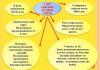
To clarify the properties of abstract automata, a classification has been introduced.
Abstract automata form a fundamental class of discrete models both as a model in its own right, and as a core component of Turing machines, push-down automata, finite automata, and other information converters.
Write a review on the article "Abstract automaton"
An excerpt characterizing the Abstract automaton
The sovereign turned to one of his entourage with a smile, pointing to the fellow Absherons, and said something to him.Kutuzov, accompanied by his adjutants, rode at a pace behind the carabinieri.
Having traveled half a verst at the tail of the column, he stopped at a lonely abandoned house (probably a former tavern) near the fork of two roads. Both roads descended downhill, and troops marched along both.
The fog began to disperse, and indefinitely, at a distance of two versts, enemy troops could already be seen on opposite hills. To the left below the shooting became more audible. Kutuzov stopped talking to the Austrian general. Prince Andrei, standing somewhat behind, peered at them and, wanting to ask the adjutant for a telescope, turned to him.
“Look, look,” this adjutant said, looking not at the distant army, but down the mountain in front of him. - They're French!
Two generals and adjutants began to grab the pipe, pulling it out one from the other. All the faces suddenly changed, and horror was expressed on everyone. The French were supposed to be two miles away from us, but they appeared suddenly, unexpectedly in front of us.
- Is this an enemy? ... No! ... Yes, look, he ... probably ... What is this? voices were heard.
Prince Andrey with a simple eye I saw below to the right a dense column of French rising towards the Apsheronians, no further than five hundred paces from the place where Kutuzov was standing.
“Here it is, the decisive moment has come! It came to me, ”thought Prince Andrei, and hitting his horse, drove up to Kutuzov. “We must stop the Apsheronians,” he shouted, “your excellency!” But at the same moment, everything was covered in smoke, close-range shooting was heard, and a naively frightened voice, two steps away from Prince Andrei, shouted: “Well, brothers, the Sabbath!” And as if this voice was a command. At this voice, everything rushed to run.
Mixed, ever-increasing crowds fled back to the place where five minutes ago the troops passed by the emperors. It was not only difficult to stop this crowd, but it was impossible not to move back together with the crowd.
Bolkonsky only tried to keep up with her and looked around, perplexed and unable to understand what was happening in front of him. Nesvitsky, with an angry look, red and not like himself, shouted to Kutuzov that if he did not leave now, he would probably be taken prisoner. Kutuzov stood in the same place and, without answering, took out his handkerchief. Blood was flowing from his cheek. Prince Andrei pushed his way up to him.
- Are you injured? he asked, barely able to control the trembling of his lower jaw.
- The wounds are not here, but where! - said Kutuzov, pressing a handkerchief to his wounded cheek and pointing to the fugitives. - Stop them! he shouted, and at the same time, probably convinced that it was impossible to stop them, he hit his horse and rode to the right.
Self-study circuitry. Abstract automaton. Part 2
- Electronics for beginners
The article is written, collected and typeset. Thank him very much.
In the previous article, I tried to lay out all the basic definitions and principles in order to make this article as clear as possible. Everything did not fit, so I strongly advise you to familiarize yourself with these files:
Basis , Basis2 , Minimization . Later in this article, I left a few explanatory notes in italics.
In this article I will try to explain in plain language what is an abstract automaton, ways of its representation. Since automata theory is full of mathematics and complex, I will try to write human language so that the unprepared reader can understand what is at stake.
Electronic digital circuits can be formally divided into 2 classes:
- Combination Schemes (CS) - do not have memory. The output signal is formed depending on combinations input data at a fixed point in time (taking into account the delay in signal conversion). Combination circuits, their types and construction principles can be a topic for a separate article, and examples include: Controlled buses, multiplexers and demultiplexers, decoders and encoders, code converters, combinational counters and adders, etc.
- Memory circuits - the algorithm of their work depends on the state of the inputs and memory(what was in the previous moments of time). These schemes are described using the theory of finite automata. We will talk about them further.
Abstract automaton
The machine will have to implement some of the functions that are set by the developer. It can be a simple adder, it can implement any processor microinstruction, it can select words from random access memory or parse the expression.IN general view, without going into details, the abstract automaton can be represented as follows:

Or, if we move from illustration to mathematical description:
A=
Designations:
- Set (A) is a set of values at the physical inputs of the automaton. At the input in our case there will be some sequence of high and low levels voltages that will encode logical zeros and ones.
- Set (B) is a set of values at the physical outputs of the automaton.
- Set (C) - a set that represents the internal state of the automaton - memory. For the future, C0 will be denoted initial state machine.
- δ = X × Z → Z are the transition functions of the automaton; they uniquely determine the state ai into which the automaton passes from state aj.
- λ = X × Z → Y are output functions, they determine what is at the output of the automaton depending on the inputs and the internal state.
Such an automaton functions discretely in time, that is, the values of inputs, outputs, and the internal state of the automaton change at discrete times.
So we have generally described what is an Abstract automaton. An example of such an automaton can be a trigger, a computer register or an adder.
There are 2 types of machines:
- Mealy machines. Described by the system of equations:
c(t) = δ(a(t), c(t-1));
b(t) = λ(a(t), c(t-1)). - Moore automata. Described by the equations:
c(t) = δ(a(t), c(t-1));
b(t) = λ(a(t), c(t)).
Automata differ in the type of exit function. In a Mealy machine, the output signal is determined by the input signal a(t) and the state of the machine at the previous time c(t-1). The output signal of the Moore machine is determined by the pair of input signal a(t) and the state in this moment c(t).
It can also be noted that one can go from one type to the second and vice versa, and in the transition from the Mealy automaton to the Moore automaton, the number internal states the automaton will remain the same, and in the reverse transition the number of internal states may increase. We will not dwell on this in detail, considering that we have synthesized (drawn a graph) an automaton of the type that is needed.
So, this is the end of the materiel. Let's try to describe the automata.
Those. A Mealy-type automaton generates an output signal when its input changes, depending on its previous state. In this case, the duration of the output signal does not depend on the duration of the input, but only on its presence. In Moore-type automata, the output signal depends on the state of the automaton at the current time, i.e. the automaton will produce a certain output signal until it changes its state.
Methods for setting automata
As we found out in the first part, the automaton is a set of input and output alphabets, a set of internal states and functions that determine transitions and outputs. However, usually the functions δ and λ are not given, and the behavior of the automaton has to be described differently.There are two main ways to define an automaton:
- With the help of graphs.
- With the help of jump tables and outputs.
Counts
The graph of an automaton is a directed connected graph, the vertices of which symbolize the internal states of the automaton, and the arcs symbolize transitions from one state to another.
For the Mealy graph, similar and output letters are indicated on the arcs. The output letters are written above the arcs, symbolizing that the output state depends on the state of the automaton at the previous moment in time.

For a Moore automaton graph, only input letters are written on arcs, while output letters are indicated near the vertices.
An important point: If as many arcs emerge from each vertex as there are input letters, then the automaton is called complete. In other words, if transitions are defined from each vertex for each input letter. In our examples, the machine Miles is full, and the automaton Mura - partial.
And one more thing: If there are more arcs from one vertex than input letters (that is, 2 or more arcs with the same input letters), then such an automaton is called non-deterministic. This can happen when building a formalized description, and then it will be necessary to make a transition to deterministic machine, but this is not always possible. I also miss the description of this process, having immediately drawn a deterministic automaton.
That's all about graphs.
Jump and output tables.
Graphs are more visual for a person, and tables are for a machine. Any automaton can be represented as a transition and output table (TOT). In TPV, the rows are the internal states of the automaton, and the columns are the input letters.Let us construct the TPV for our Mealy and Moore graphs. If any input or output letter is not defined, then a dash is put instead. If the state is not defined, then the same simple rule applies.
Count Miley TPV
In Mile's TPV, transitions and exits are recorded in each cell. For example, if the automaton is in state C0 and the letter a1 comes to the input, then it will go to state C1 and the letter b3 will appear at the output.
Count Moore TPV
For the Moore graph, a marked transition table is built. An additional column is allocated for output letters.In the cell under the input letter it is written what state the automaton goes into, in the rightmost cell - what output letter it returns.

An example of automaton synthesis
Using abstract automata, you can describe almost anything. You can describe the operation of a digital circuit, or you can describe a parser or lexical analyzer. Let's try to describe the trigger - why not an automaton?To set a graph, you need a verbal description of the algorithm of the trigger. Reading:
We encode the input and output alphabets:
A = (a0, a1), where a0 is a logical 1 at input R, a1 is a logical one at input S.
B = (b0, b1), where b0 is a logical 0 at output Q, b1 is a logical one at output Q.
We build a Mealy automaton graph: 
Here is such a funny cheburashka turned out :-). Now we can build the transition and exit table: 
If you write this table by transforming conventions into actual ones, we get a table which is a table of trigger transitions. Then it can be simplified: 
We apply the resulting function to the Veitch map and minimize it:

Let's write down what happened: ![]()
We build a scheme by function (Did you do your homework?).
A digital (discrete) automaton can be interpreted as a device that receives, stores and converts discrete information according to some algorithm. From a certain point of view, automata can include both real devices (computers, living organisms, etc.) and abstract systems (mathematical machines, axiomatic theories
general theory Automata are divided into abstract and structural. The difference between them lies in the fact that the abstract theory, abstracting from the structure of the automaton (i.e., not being interested in the way it is constructed), studies only the behavior of the automaton with respect to external environment. The abstract theory of automata is close, therefore, to the theory of algorithms, being in essence its further detailing. In contrast to the abstract theory, the structural theory is interested both in the structure of the automaton itself and in the structure of the input actions and the automaton's reactions to them. Structural theory studies methods for constructing automata, methods for coding input actions and reactions of an automaton. Thus, the structural theory of automata is a continuation and further development abstract theory. Based on the apparatus of Boolean functions and on the abstract theory of automata, the structural theory gives effective recommendations on the development of real computing devices.
An abstract digital automaton A is defined by a set of five objects where is the set of input signals of automaton A (the input alphabet of automaton A); - set of states of automaton A (alphabet of automaton states - set of output signals of automaton A (output alphabet of automaton A); - transition function
![]()

automaton A, which specifies a mapping, i.e., assigning to any pair of elements of the Cartesian product of sets, an element of the set is an output function of the automaton A, which specifies either a mapping or a mapping
In other words, the transition function shows that the automaton A, being in a certain state when the input signal appears, goes into a certain state. The latter can also be written as an expression. The output function that specifies the mapping shows that the automaton L, being in a certain state when the input signal appears, produces an output signal. The latter can be written as
According to the method of generating the output function, three types of abstract automata are distinguished: Mealy automaton, Moore automaton, C-automaton. In the abstract Mealy automaton, the output function X defines the mapping . In the abstract Moore automaton, the output function defines the mapping; in the abstract C-automaton, two output functions X, and defining the mapping, respectively, are introduced. In this case, the output alphabet of the C-automaton is either
An arbitrary abstract Milan or Moore automaton has one input and one output channel (Fig. 10.1). An arbitrary abstract C-automaton has one input and two output channels (Figure 10.2).
There are fully defined and partial automata.
Fully defined is an abstract digital automaton whose transition function and output function are defined for all pairs
An abstract digital automaton is called partial if the transition function or the output function, or both of these functions, are not defined for all pairs
An abstract digital automaton is called initial if a special initial state is allocated on the set of its states 5, i.e., the initial abstract automaton is determined by a set of six objects. The selection on the initial state set is explained by purely practical considerations related to the often arising need to fix the conditions for the start of the automaton.
An abstract automaton is said to operate in discrete automaton time, and transitions from state to state are instantaneous. At each moment of discrete time, the automaton is in some state from the set of states. If the automaton is initial, then at the initial moment of time it is always in the initial state . At the moment being in the state, the automaton is able to accept at the input the letter of the input alphabet in accordance with the output function X, it will give out at the same time the letter of the output alphabet and, in accordance with the transition function, will go to the
state According to the definition of an abstract automaton, the Mealy automaton in this case is characterized by a system of equations:
![]()
Moore's automaton - by a system of equations;
![]()
and the C-automaton - by a system of equations:

In other words, if the initial abstract Mealy or Moore automaton, set to the initial state, is fed letter by letter with some sequence of letters of the input alphabet of the input word, then the letters of the output alphabet of the output word will appear sequentially at the output of the automaton. For the case of a C-automaton, two sequences will appear at its outputs: in an abstract C-automaton, the output signal is given all the bonuses while the machine is in the state
Thus, at the level of abstract theory, the functioning of a digital automaton is understood as a transformation of input words into output words.
The concept of state in the definition of an abstract automaton was introduced due to the fact that most of the real processes that are controlled by actually built digital automata require knowledge of the prehistory of the process development in time for their correct flow. In other words, the output signal issued by the automaton at a given moment of time is determined not only by the input action on the automaton, but also by the state in which the automaton was at that moment in time. only the “switch the traffic light” signal, then at each moment in order to organize the correct operation of the machine, in addition to the input signal “switch the traffic light”, it is necessary to have information about the position of the traffic light at the previous moment of time. This information is provided by the presence of various states of the abstract automaton. Abstract digital automata corresponding to the introduced definition of an abstract automaton are also called abstract automata with memory, since the existence of a set of different states in an automaton is possible only if the automaton has memory.
A number of processes controlled by real automata do not require knowledge of the prehistory of the development of the process in time for their correct course. In automatic machines that control such processes,
Table 10.1

the output signal is determined only by the input action on the automaton. These automata are defined at the abstract representation level using the triple , where the output function defines the mapping, and are called abstract automata with trivial memory or combinational automata. The simplest analogue of a combinational automaton can be read as an ordinary electric lamp, provided that the input action is pressing the "On" button, and the output signal is the ignition of the lamp bulb.
The alphabets of inputs, states, and outputs of automata are specified as ordinary sets, for example, by listing their elements. Transition and output functions can be specified matrix, graphically and analytically. Therefore, any abstract automaton can be defined in three ways! matrix, graphically and analytically
With the matrix method, the automaton is represented either by two tables: a transition table and an output table, or a connection matrix. The transition table specifies the mapping, i.e., determines the transition function of the automaton. machine output function.
The transition table of an arbitrary fully defined abstract automaton is constructed as follows. The columns of the table are labeled with the letters of the input alphabet of the automaton, and the rows of the table are labeled with the letters of the alphabet of the states of the automaton. In the cell of the transition table located at the intersection of the column marked by the input signal and the row marked by the state, the state is set, which is the result of the transition of the automaton from the state under the influence of the input signal, which is determined by the expression Example, the transition table of some abstract fully defined automaton with an input alphabet and an alphabet of states is tab. 10.1. If the abstract automaton is partial, then a dash is placed in the cell of its transition table located at the intersection of the column marked by the input signal and the row marked by the state (provided that the transition from the state under the influence of the input signal is undefined), and any input word leading to specified transition is prohibited. Filling in the rest of the cells is similar to the case of a fully defined automaton. An example of a transition table for some abstract partial automaton with an input alphabet and an alphabet of states is presented in Table. 10.2. The form of the transition table does not depend on the type of the given automaton (Moore automaton, Mealy automaton, C-automaton). The output tables of the Moore, Mealy, C-automaton have differences. The output table of a fully defined Mealy machine is constructed as follows. The identification of columns and rows and the format of the table correspond to the jump table of a fully defined automaton. In the cell of the output table,
Table 10.2

Table 10.3

Table 10.4

located at the intersection of the column marked by the input signal and the row marked by the state, the output signal is set, which the Mealy machine produces, being in a state in the presence of the input signal, which is determined by the expression tab. 10.3.
The output table of a fully defined Moore automaton is constructed more simply: each state of the automaton is assigned its own output signal. An example of a Moore machine output table with state alphabet and output alphabet is shown in Table 10.4.
Obviously, an abstract fully defined C-automaton is given by two output tables, the first of which is the output table of the Mealy automaton, and the second is the output table of the Moore automaton.
If the Mealy automaton is partial, then in some cells of its table of outputs there may be a dash, indicating the absence of an output signal. In this case, a dash must be placed in those cells of the output table that correspond to the same cells with a dash in the transition table of the Mealy automaton. The latter is due to the fact that if in the partial Mealy automaton there is a pair ) and such that the transition from the state under the influence of the input signal is undefined, then, naturally, the value of the output signal at such a (nonexistent) transition is also undefined. An example of a table of outputs of a partial Mealy automaton, given by a transition table (Table 10.2) with an output alphabet, is presented in Table. 10.5
The dashes in some cells of the output table of a partial Moore automaton are not related to the dashes in the cells of its transition table. This is determined by the fact that the output signal of the Moore machine depends only on the state in which the machine is located. For example, the output table of a partial Moore machine given by the transition table (Table 10.2),
Table 10.5

Table 10.6.

Table 10.7

can also be presented as a table. 10.4, if in each of its states the machine produces some kind of output signal, and as in Table. 10.6, if the value of the output signal of the automaton for some states is undefined.
In practice, the transition and output tables of an automaton are often combined into one table, called the labeled transition table of the automaton. The marked transition table of a fully defined Mealy automaton, represented by the transition table (Table 10.1) and the output table (Table 10.3), is summarized in Table. 10.7. The marked transition table of the partial Moore automaton (Table 10.2) and the output table (Table 10.4) are summarized in Table. 10.8.
In addition to the transition and exit tables discussed above, an arbitrary abstract automaton can be described by a connection matrix. Such a description is one of the methods for the matrix definition of abstract automata. The connection matrix of an arbitrary abstract automaton is square and contains as many columns (rows) as there are different states of the automaton under consideration. Each column (row) of the matrix of connections is marked with the letter of the automaton state. If the automaton is initial, then the first column from the left and the first row from the top of the matrix of its connections are marked with the letter of the initial state of the automaton , under the influence of which the transition of the automaton from state to state is carried out. If the abstract Milne automaton is specified by the connection matrix, then next to the letter of the input signal in brackets is indicated the letter of the output signal that the Mealy machine produces when making the transition. . 10.7) is shown in fig. 10.3.
If the connection matrix is an abstract Moore automaton, then the output signals mark the states of the automaton that identify the rows of the connection matrix.
Table 10.8


At graphical way jobs abstract automata are represented by directed graphs; the states of the automaton are represented by the vertices of the graph, and the transitions between the states are represented by arcs between the corresponding vertices. In this case, each arc of the graph is assigned a certain letter of the automaton's input alphabet, indicating that this transition of the automaton is carried out only when an input signal appears and each vertex of the graph is assigned a letter of the corresponding state of the automaton. If the graph represents the Mila automaton, then the output signals of the automaton are put down on the arcs of the graph (in accordance with the table of outputs of the automaton) next to the letter of the input signal. An example of a Mealy automaton graph defined by a transition table (Table 10.1) and an output table (Table 10.3) is shown in Fig. 10.4. If the graph represents a Moore automaton, then the output signals of the automaton are placed near the vertices of the graph (in accordance with the table of outputs of the automaton). An example of a Moore automaton graph defined by a transition table (Table 10.2) and an output table (Table 10.4) is shown in Fig. 10.5.
With the analytical method of setting, abstract automata are represented by a four objects where specifies the mapping for each state of the automaton. In other words, in the analytical way of specifying for each state of the automaton, a mapping is indicated that is a set of all triples and such that, under the influence of the input signal, the automaton performs a transition from state to state, while issuing an output signal. common definition abstract automaton, the latter is equivalent to the description of functions and X in accordance with the expressions: Mapping is written as follows:
The analytical task of the Mealy automaton, represented by the marked transition table (Table 10.7), has the following form.

Consider an equivalent transformation of automata. Equivalent automata are those that induce the same mapping from the set of words in the input alphabet to the set of words in the output alphabet. Consider only the transformation of a Moore automaton into its equivalent Mealy automaton. The transformation of a Mealy automaton into an equivalent Moore automaton is somewhat more complicated.
The transition from the Moore automaton to the equivalent Mealy automaton is conveniently carried out with the graphical method of specifying the automata. In this case, it reduces to transferring the output signal given by the Moore automaton in the state to the arcs included in the vertex marked with the letter. In the matrix method, the transition table of the Mealy automaton coincides with the transition table of the Moore automaton, and the table of outputs of the Mealy automaton is obtained from its transition table by replacing the letter of the state located at the intersection of the column marked by the input signal and the row to the output signal issued by the Moore automaton in the state
Development real machines(represented at least at the level of fundamental electrical circuits) requires their setting first at the abstract level, followed by a transition to the structural level, which takes into account the logical elements used in the automaton circuit and the connections between them. In this regard, the task of synthesizing an abstract automaton arises, based on some initial, for example, verbal description of its operation. Existing algorithms for the synthesis of abstract automata are usually not used in practice due to the complexity and cumbersomeness of calculations and therefore are not included in the textbook material. However, for a better understanding of the concept of an abstract automaton and how to define it, we will consider here an example of the synthesis of an abstract automaton, based on purely speculative considerations.
Example. Build an abstract digital automaton for controlling the switching of a traffic light, provided that only the signal “switch the traffic light” is received at the input of the automaton. We denote this signal by a letter and its absence by a letter.


Obviously, the input alphabet X of such an automaton will consist of two letters: green color, then we introduce three corresponding output control signals. We also assume that at the moment of the start of operation, the automaton is in the state The operation algorithm is trivial; A possible solution for the Mealy machine is shown in Fig. 10.6, and for the Moore machine - in fig. 10.7. For (simplification, we assume that at the initial moment of time, the Moore automaton gives the output signal “turn on the green color”. Note that to build the automaton graph, you need to enter four different states. The number of states can be reduced, for example, by increasing the number of input signals of the automaton or by expanding the capabilities of the automaton in in terms of storing the prehistory of the development of the control process in time (in the example under consideration, only the moment of issuing the last output signal is remembered).
In conclusion, we note that we consider only deterministic automata for which the condition of uniqueness of transitions is satisfied: an automaton that is in a certain state cannot go to more than one state under the action of any input signal. The automaton specified by the transition table is always deterministic, since at the intersection of the column and row of the transition table, only one state is recorded if the transition is defined, and a dash is put if the transition is not defined. With regard to the graphical method of defining an automaton, the uniqueness condition means that two or more arcs marked by the same input signal cannot emerge from any vertex in the automaton graph.
- 1.1 Basic concepts
- Conclusion
- Bibliography
Introduction
Subject control work in the discipline "Applied theory of digital automata" - "Abstract digital automata".
The purpose of the work is to get acquainted with the basic concepts of abstract digital automata; types of abstract automata; ways of specifying abstract automata; connection between Mealy and Moore models; equivalent automata and equivalent transformations of automata; minimization of the number of internal states of the automaton and the Aufenkamp-Hohn algorithm.
1. Abstract digital automata
1.1 Basic concepts
A digital automaton can be interpreted as a device that receives, stores and converts discrete information according to some algorithm. From a certain point of view, both real devices (computers) and abstract systems (mathematical models) can be attributed to automata.
An automaton is a discrete information converter capable of accepting various states, moving from one state to another under the influence of input signals, and producing output signals.
The general theory of automata is subdivided into abstract and structural.
The abstract theory of automata, disregarding the structure of the automaton (that is, without being interested in the way it is constructed), studies only the behavior of the automaton relative to the external environment. The abstract theory of automata is close to the theory of algorithms, being in essence its further realization.
In contrast to the abstract theory of automata, the structural theory of automata is interested both in the structure of the automaton itself and in the structure of input actions and reactions of the automaton to them. Structural theory studies methods for constructing automata, methods for coding input actions and automaton reactions to them. The structural theory of automata is a continuation and development of the abstract theory. Relying on the apparatus of Boolean functions and on the abstract theory of automata, the structural theory gives effective recommendations for the development of real computing devices.
An abstract digital automaton (DA) is a mathematical model of a discrete control device.
An abstract target audience is defined by a set consisting of six elements:
S=(X,A,Y,ao),
Where:
X=(x1, x2,. xn) - set of input signals (input alphabet);
Y=(y1, y2, ym) - set of output signals (output alphabet);
А=( a0, a1, a2,. aN) - set of states (alphabet of states);
ao - initial state (aoA);
- the transition function of the automaton, which specifies the mapping (XxA) A, i.e. assigning to any pair of elements of the Cartesian product (XxA) an element of the set A;
- automaton output function specifying either the mapping (XxA) Y or the mapping AY.
In other words, the transition function shows that the automaton S, being in a certain state ajA, when an input signal xjX appears, passes to a certain state apA. This can be written:
ap= (ai,Xj).
Output function shows that the automaton S, being in a certain state ajA, when an input signal xjX appears, produces an output signal ykY. This can be written: уk = (ai , Xj).
The concept of state was introduced into the definition of an automaton due to the fact that it often becomes necessary to describe the behavior of systems whose outputs depend not only on the state of the inputs at a given time, but also on some prehistory, i.e. from the signals that came to the inputs of the system earlier. The state just corresponds to some memory of the past, allowing time to be eliminated as an explicit variable and output signals to be expressed as a function of states and inputs at a given time.
The abstract automaton functions in discrete automaton time t=0,1,2,. and transitions from state to state are instantaneous. At each moment t of discrete time, the automaton is in a certain state a (t) from the set A of states of the automaton, and at the initial time t=0 it is always in the initial state ao. At the time t, being in the state a (t), the automaton is able to perceive the signal x (t) X on the input channel, and output the signal y (t) = (a (t), x (t)) on the output channel, passing to the state a (t+1) = = (a (t),x (t)). The dependence of the output signal on the input and on the state means that it contains memory.
1.2 Types of abstract automata
According to the method of generating the output function, three types of abstract automata are distinguished: Mealy automaton, Moore automaton, C-automaton. The Mealy automaton is characterized by a system of equations:
y(t) = (a(t), x(t));
a(t+1) = q(a(t), x(t)). (1-1)
Moore automaton - system of equations:
y(t) = (a(t));
a(t+1) = q(a(t), x(t)). (1-2)
C-machine - system of equations:
y=y1y2
y1(t) = (a(t),x(t));
Y2(t) = 2(a(t));
a (t+1) = q (a (t), x (t)).
An arbitrary abstract Mealy or Moore automaton (Fig. 1.1.) has one input and one output channel. An arbitrary abstract C-automaton has one input and two output channels (Fig. 1.2.).
Figure 1.1 - Abstract automaton
Figure 1.2 Abstract C-automaton
If the input of an abstract Mealy or Moore automaton, set to the initial state ao, is given letter by letter some sequence of letters of the input alphabet x(0), x(1),. is an input word, then the letters of the output alphabet y (0), y (1), will appear sequentially at the output of the automaton. - output word. For the case of a C-automaton, two sequences will appear at its outputs: y1 (0), y1 (1),. and y2(0), y2(1), . In an abstract C-automaton, the output signal y2 (t) = (a (t)) is emitted all the time while the automaton is in the state a (t). The output signal y1 (t) =l1 (a (t), x (t)) is issued during the action of the input signal x (t) when the C-automaton is in the state a (t).
Thus, at the level of abstract theory, the functioning of a digital automaton is understood as a transformation of input words into output words.
There are fully defined and partial automata.
An abstract digital automaton is called completely defined if its transition function or output function or both of these functions are defined for all pairs of transitions (xi,aj).
An abstract digital automaton is called partial if the transition function or the output function, or both of these functions, are not defined for all pairs of transitions (xi,aj).
An abstract digital automaton is called initial if on the set of its states A the initial state ao is distinguished.
1.3 Ways to define abstract automata
To set a finite automaton S, it is necessary to describe all elements of the set: S=( X,A,Y,ao). There are several ways to set the operation of the machine, but the most commonly used are tabular (matrix), graphical, and analytical.
With the tabular method, the automaton is specified by two tables: a transition table and an output table, or a connection matrix. The transition table of an arbitrary fully defined automaton is constructed as follows: the rows of the table are marked with the letters of the input alphabet of the automaton, and the columns of the table are marked with the letters of the automaton state alphabet; In the cell of the jump table located on at the intersection of the row marked with the input signal xi and the column marked with the state aj, the state ak is set, which is the result of the transition of the automaton from the state aj under the influence of the input signal xi, which is determined by the expression ak= (aj, xj).
Table 1.1 Automaton transition table
An example of filling in the transition table of some abstract fully defined automaton with the input alphabet X=(x1, x2) - and the state alphabet A=(a1, a2, a3) is presented in Table 1.2.
Table 1.2
If the abstract automaton is partial, then a dash is placed in the cell of its transition table located at the intersection of the row marked with the input signal and the column marked with the corresponding state (provided that the transition to this state under the action of this input signal is not defined), and any input word leading to the specified transition is forbidden.
Filling in the rest of the cells is similar to the case of a fully defined automaton. The form of the transition table does not depend on the type of the given automaton (Mealy, Moore, C-automaton). The output tables of Mealy, Moore, C-automata have differences.
The output table of a fully defined Mealy automaton is constructed as follows: the column and row identifications and the format of the table correspond to the transition table of a fully defined automaton. In the cell of the output table located at the intersection of the row marked with the input signal Xj and the column marked with the state ak, the output signal Um is placed, which the automaton issues when it is in the state ak in the presence of the input signal Xj, which is determined by the expression Ym= (ak, xj ).
Table 1.3 Table of outputs of the abstract Mealy automaton.
An example of filling in the output table of some abstract fully defined automaton with input alphabet X=(x1, x2), state alphabet A=(a1, a2, a3) and output alphabet Y=(y1, y2, y3) is presented in Table 1.4.
Table 1.4
Obviously, an abstract fully defined C-automaton is given by two output tables, the first of which is the output table of the Mealy automaton, and the second is the Moore output table. If the automaton is partial, then in some cells of its table there may be a dash, which means there is no output signal.
In practice, the transition and output tables are often combined into one table, called the labeled transition table of the automaton. Examples of marked transition tables are presented in Table 1.6. - 1.8 (General view of the marked transition table - Table 1.6., Marked transition table of the Mealy machine - Table 1.7., Marked transition table of the Moore machine - Table 1.8.).
In addition to the transition and output tables discussed above, an arbitrary abstract automaton can be defined by a connection matrix.
The connection matrix is square and contains as many columns (rows) as there are different states in the state alphabet of the given automaton. Each column (row) of the matrix of connections is marked with the letter of the automaton state. In the cell located at the intersection of the column marked with the letter aj and the row marked with the letter as of the automaton, an input signal (or a disjunction of input signals) is placed, under the influence of which this transition is carried out.
For an abstract Mealy automaton, the cell next to the state also contains the output signal that the automaton issues as a result of this transition (Table 1.9.) For the Moore automaton, the output signal is put in the line next to the state (these states correspond to the initial states of the automaton).
Table 1.6
Table 1.8
In the graphical way of setting, abstract automata are represented by directed graphs. An automaton graph is a directed connected graph whose vertices correspond to automaton states, and the arcs between them correspond to transitions between states. Two vertices ak and as are connected by an arc if the automaton has a transition from state ak to state as. For a Mealy machine, the input and output signals are placed on an arc corresponding to this transition(Fig. 1.3.), for the Moore automaton, the input signal is placed on the arc, and the output signal is placed near the vertex corresponding to the state (Fig. 1.4.).
Here, only deterministic automata are considered, for which the condition of uniqueness of transitions is satisfied: an automaton, which is in a certain state, under the action of any input signal cannot go to more than one state. With regard to the graphical method of specifying the automaton, this means that two or more arcs marked by the same input signal cannot emerge from any vertex in the automaton graph.
Figure 1.3-Graph of a Mealy machine Figure 1.4-Graph of a Moore machine
In the analytical way of setting, abstract automata are given by four objects:
S=( X,A,Y,F), where F defines for each state aj of the automaton the mapping (ХхА) - > (AxY). In other words, in the analytical way of specifying for each state of the automaton aj, the mapping Fai is indicated, which is the set of all triplets ap, xm, yk, and such that under the influence of the input signal xm the automaton passes from the state Aj V state ap, producing an output signal yk.
With regard to the general definition of an abstract automaton, the latter is equivalent to describing the functions q and l in accordance with the expression: ap= q (ai, xm), yk= l (ai, xm).
The Fai mapping is written as follows:
Fai(ap (Xm/yk),ai (Xf/yz) …).
For the abstract Mealy automaton (Table 1.7.), the analytical task has the following form:
S=(X,A,Y,F), X=(x1,x2), A=(a1, a2, a3), Y=(y1, y2, y3),
Fa1=(a2 (x1/y2), a1 (x2/y3) ),
Fa2=(а3 (x1/y3), a1 (x2/y1) ),
Fa3=(a1 (x1/y3), a2 (x2/y2) ).
It should be noted that the Fai function is always written for the initial state.
We define synchronous and asynchronous automata. A state as of an automaton S is called a stable state if for any input signal xjX such that as = q (ai Xm) we have as = q (as, xm).
An automaton S is called asynchronous if each of its states as A is stable. An automaton S is called synchronous if it is not asynchronous.
It should be noted that automata built in practice are always asynchronous and the stability of their states is always ensured in one way or another, for example, by introducing synchronization signals. However, at the level of abstract automata theory, when an automaton is just a mathematical model that does not reflect many specific features of its implementation, it often turns out to be more convenient to operate with synchronous automata.
1.4 Relationship between Mealy and Moore models
As already noted, the abstract automaton works as a converter of words in the input alphabet into words in the output alphabet.
Let the Mealy abstract automaton be given by the graph in Fig. 1.5.
The input of this automaton, set to the initial state, receives the input word X=x1, x1, x2, x1, x2, x2.
Figure 1.5 - Graph of the Mealy automaton
Because? (a1, x1) = a3, a? (a1, x1) = y1, then under the action of the first letter of the word X of the input signal x1, the automaton will go to the state a3 and the signal y1 will appear at its output. Further, ? (a3, x1) = a1, huh? (a3, x1) = y2, therefore, when the second signal x1 arrives, the automaton will be in the state a1, and the signal y2 will appear at its output. Following directly on the graph or tables of transitions and outputs, the further behavior of the automaton, we describe it in three lines, the first of which corresponds to the input word X, the second - the sequence of states that the automaton goes through under the action of the letters of the word X, the third - to the output word Y, which appears at the output machine:
x1x1 x2 x1 x2 x2
a1a3 a1a1 a3 a2 a3
y1 y2 y1 y1 y1 y2
Let's call y = ? (a1, X) by the reaction of the Mealy machine in state a1 to the input word X. As can be seen from the example, in response to the input word of length k, the Mealy machine produces a sequence of states of length k + 1 and an output word of length k. In general, the behavior of the Mealy automaton, set to the state am, can be described as follows:
In the same way, one can describe the behavior of the Moore automaton, which is in the state am, when the input word xi1, xi2,., хik arrives . Recall that, in accordance with (1-2), the output signal in the Moore automaton at time t (Y (t)) depends only on the state in which the automaton is at time t (a (t)):
Obviously, the output signal yi1=l (am) at time i1 does not depend on the input signal xi1, but is determined only by the state am.
Thus, this signal yi1 is in no way connected with the input word coming to the input of the automaton, starting from the moment i1. In this regard, under the reaction of the Moore machine set to the state am to the input word X=xi1, хi2 , . , хik we will understand the output word of the same length y= л(am,х)=уi2, уi3,., yik+1.
As an example, consider the Moore machine S5, the graph of which is shown in Fig. 1-6, and find its response in the initial state to the same input word that we used when analyzing the behavior of the Mealy machine S1:
Figure 1-6 - Moore automaton graph
As can be seen from this and the previous examples, the reactions of the automata S5 and S1 in the initial state to the input word X coincide up to a shift of 1 cycle (the reaction of the Moore automaton is circled). We now give a rigorous definition of the equivalence of fully defined automata.
Two automata SA and SB with the same input and output alphabets are called equivalent if, after setting them to the initial states, their reactions to any input word coincide.
1.5 Equivalent automata. Equivalent transformations of automata
It can be shown that for any Mealy automaton there exists an equivalent Moore automaton and, conversely, for any Moore automaton there exists an equivalent Mealy automaton.
In describing the algorithms for the mutual transformation of Mealy and Moore automata in accordance with the above, we will neglect the output signal in Moore automata associated with the initial state (? (a1)).
Consider first the transformation of a Moore machine into a Mealy machine.
Let a Moore automaton be given: SA=(XA, AA, UA,?A,?A, aoA), where:
XA=(x1, x2, xn); Y=(y1, y2, ym); A=( a0, a1, a2, aN); a0A = a0 - initial state (a0AA); ?A - automaton transition function that defines the mapping (ХАхАА) - >АА; ?A - function of the outputs of the automaton, which sets the mapping AA->UA.
Let's build a Mealy automaton: SB=( XB, AB, YB,??B, ?B , a0B), in which AB=AA; XB=XA; YB=UA; ?B=?A; a0B=a0A. The output function?B is defined as follows. If in the Moore machine? A (am, x1) = as and? A (as) = yg, then in the Mealy machine? B (am, x1) = yg
Figure 1.7 - Illustration of the transition from the Moore model to the Mealy model
The transition from the Moore automaton to the Mealy automaton with a graphical way of setting is illustrated in Fig. 1-7: the output signal yg written near the vertex (as) is transferred to all arcs included in this vertex.
With the tabular method of specifying the automaton, the transition table of the Mealy automaton coincides with the transition table of the original Moore automaton, and the output table is obtained from the transition table by replacing the symbol as at the intersection of the row xf and column am with the symbol of the output signal yg marking the column as in the transition table of the automaton SA.
From the way the Mealy automaton SB is constructed, it is obvious that it is equivalent to the Moore automaton SA. By induction, it is easy to show that any input word of finite length, given to the inputs of the automata SA and SB, set to the states am, will cause the appearance of the same output words and, therefore, the automata SA and SB are equivalent.
Before considering the transformation of the Mealy machine into a machine Moore, we impose the following restriction on the Mealy automaton: the automaton must not have transient states. By transient we mean a state in which, when the automaton is represented as a graph, no arc enters, but which has at least one outgoing arc. So, let the Mealy automaton be given:
SA=( XA, AA,YA, ?A, ?A, a0A),
Where:
XA=(x1, x2,.xn); Y=(y1, y2, .ym); A=(a0,a1,a2,.aN); a0A = a0 - initial state (a0AA); ?A - automaton transition function that defines the mapping (XAxAA) - >AA; ?A - automaton output function that defines the mapping (XAxAA) - >YA.
Let's build a Moore automaton: SB=(XB, AB, YB, ?B, ?B, a0B), which has XB=XA; YB=YA.
To determine AB, each state asАA is associated with the set As of all possible pairs of the form (as, yg)
The output function?B is defined as follows. Each state of the Moore automaton SB, which is a pair of the form (as, yg), will be assigned an output signal yg.
If the Mealy automaton SA had a transition?A (am, xf) = as and at the same time produced an output signal?A (am,xf) =yg, then in SB there will be a transition from the set of states Am generated by am to the state (as, yg) under the action of the input signal xf.
As the initial state a0B, one can take any of the states of the set A0, which is generated by the initial state a0 of the automaton SA. In this case, the output signal at time t=0 should not be taken into account.
Consider an example. Let the Mealy automaton be given (Table 1.10.)
Let us assign to each pair ai/xk the state bik (i-number of the state, k-number of the input signal), taking into account b0.
Let's make a transition table of the Moore automaton, guided by the following rules:
1) Let us write out the states of the Mealy automaton and the sets of states of the Moore automaton (bik) corresponding to each of them from Table 1.11:
a0= (b0, b02, b11, b21); a1= (b22); a2= (b01, b12);
2) If the state of the Moore machine bik is included in the set corresponding to the state ap of the Mealy machine, then in the row of the transition table of the Moore machine for the state bik one should write the line from the transition table of the Mealy machine corresponding to the state ap (from 1.10.).
3) The output function of the Moore automaton is defined as follows: ?B (bik) =?A (ai, xk). For the initial state b0, the value of the output signal can be chosen arbitrarily, but generated by the initial state a0 (taking into account the concept of state equivalence). The resulting table of transitions and outputs of the Moore automaton equivalent to the Mealy automaton given in Table 1.10 is presented in Table 1.12.
4) Find equivalent states in Table 1.12 and remove them (replace them with a representative of the equivalence class).
If the output signal near b0 is extended by y1, then it turns out that in this transition table there are 3 equivalent states (b0,b11,b02). Replacing the equivalence class with one representative (b0), we obtain the final transition table (Table 1.13).
Table 1.12
The presented methods of mutual transformation of Mealy and Moore automata show that during the transition from the Moore automaton to the Mealy automaton, the number of states of the automaton does not change, while during the reverse transition, the number of states in the Moore automaton, as a rule, increases.
Thus, automata equivalent to each other can have a different number of states, which raises the problem of finding the minimum (with the minimum number of states) automaton in the class of automata equivalent to each other. The existence for any abstract automaton of an equivalent abstract automaton with a minimum number of internal states was first proved by Moore.
1.6 Minimizing the number of internal states of an automaton
Aufenkamp-Hohn algorithm.
The method of minimizing automaton states is based on the idea of partitioning all states of the original, abstract automaton into pairwise disjoint classes of equivalent states and replacing each equivalence class with one state (representative this class). The minimal automaton resulting from these transformations has as many states as the number of equivalence classes into which the initial states are divided.
Two automaton states am and as are called equivalent (am =as) if? (am, X) = ? (as,X) for all possible input words of length X.
If am and as are not equivalent, they are distinct. A weaker equivalence is the K-equivalence. The states am and as are K-equivalent if? (am, Xk) = ? (as, Xk) for all possible input words of length K. When minimizing the number of internal states of the Mealy automaton S=(X, Y, A, ? , ?, a0) the Aufenkamp-Hohn algorithm is used:
1. Find successive partitions?1,?2,…,?k,?k+1, sets A into classes of one-, two-,., K-, (K+1) - equivalent states until at some (K+1) step it will not turn out that?k=?k+1. In this case, the K-equivalent states are equivalent. The number of steps K, at which?k=?k+1 does not exceed N-1, where N is the number of internal states of the automaton.
2. In each equivalence class? choose one element each (representative of the class), which form sets A "of states of the minimal automaton S".
3. Function of transitions?" and exits?" automaton S" is defined on the set A"xX.
To do this, in the table of transitions and outputs, the columns corresponding to states not included in the set A "are crossed out, and in the remaining columns of the transition table, all states are replaced with equivalent ones from the set A", (representatives).
4. One of the states equivalent to the state a0 is chosen as a"0. In particular, it is convenient to take the state a0 itself.
When minimizing the Moore automaton, the concept of 0-equivalence of states and splitting the set of states into 0-classes is introduced: any states of the Moore automaton that are identically marked by output signals are called 0-equivalent. As an example, consider the minimization of a Moore automaton given a table of transitions and exits (Table 1.14).
Table 1.14
Shall we split?0:
? 0=(B1, B2, B3);
B1=(a1, a2, a8), B2=(a6, a9, a10, a11, a12), B3=(a3, a4, a5, a7).
Let's build a partition table?0:
Shall we partition?1:
1=(C1, C2, C3, C4);
C1=(a1, a2, a8), C2=(a6, a9, a11), C3=(a10, a12), C4=(a3, a4, a5, a7).
Let's build a partition table?1:
Shall we partition?2 .
1=(D1, D2, D3, D4);
D1=(a1, a2, a8), D2=(a6, a9, a11), D3=(a10, a12), D4=(a3, a4, a5, a7).
Splitting?2 repeats splitting?1 - the splitting procedure is completed.
Let us randomly choose one representative from each equivalence class D1, D2, D3, D4 - in this case, by the minimum number: A "= (a1, a3, a6 , a10).
Removing the "extra" states from the original transition table, we determine the minimal Moore automaton (Table 1.15.)
Table 1.15.
Conclusion
In the process of performing the control work, we got acquainted with the basic concepts of abstract digital automata; types of abstract automata; ways of specifying abstract automata; connection between Mealy and Moore models; equivalent automata and equivalent transformations of automata; minimization of the number of internal states of the automaton and the Aufenkamp-Hohn algorithm - gave examples.
Bibliography
1. K. G. Samofalov, A. M. Romankevich, et al., Applied Theory of Digital Automata. - Kyiv. "Vishcha school" 1987.
2. Soloviev G.N. Computer arithmetic devices. - M. "Energy". 1978.
3. Saveliev A.Ya. Applied theory of digital automata - M. “ graduate School”. 1987.
4. Kagan B.M. Electronic computers and systems. - M. Energoatomizdat. 1985.
5. Lysikov B.G. Arithmetic and logical foundations of digital automata. - Minsk. "The Highest School". 1980.
According to the method of generating the output function, three types of abstract automata are distinguished: Mealy automaton, Moore automaton, C-automaton. The Mealy automaton is characterized by a system of equations:
y(t)=(a(t), x(t));
a (t+1) = δ (a (t), x (t)). (1-1)
Moore automaton - system of equations:
a (t+1) = δ (a (t), x (t)). (1-2)
C-machine - system of equations:
y 1 (t) =(a (t), x (t));
Y 2 (t) = 2 (a (t));
a (t+1) =δ (a (t),x (t)).
An arbitrary abstract Mealy or Moore automaton (Fig. 1.1.) has one input and one output channel. An arbitrary abstract C-automaton has one input and two output channels (Fig. 1.2.).
Figure 1.1 - Abstract automaton
Figure 1.2 Abstract C-automaton
If the input of an abstract Mealy or Moore automaton, set to the initial state a o, is given letter by letter some sequence of letters of the input alphabet x(0), x(1),. is an input word, then the letters of the output alphabet y (0), y (1), will appear sequentially at the output of the automaton. - output word. For the case of a C-automaton, two sequences will appear at its outputs: y 1 (0), y 1 (1),. and y 2 (0), y 2 (1),. In an abstract C-automaton, the output signal y 2 (t) =(a (t)) is issued all the time while the automaton is in the state a (t). The output signal y 1 (t) =λ 1 (a (t),x (t)) is issued during the action of the input signal x (t) when the C-automaton is in the state a (t).
Thus, at the level of abstract theory, the functioning of a digital automaton is understood as a transformation of input words into output words.
There are fully defined and partial automata.
An abstract digital automaton is called fully defined if its transition function or output function or both of these functions are defined for all pairs of transitions (x i ,a j).
Partial is an abstract digital automaton, in which the transition function or the output function, or both of these functions are not defined for all pairs of transitions (x i ,a j).
An abstract digital automaton is called initial if on the set of its states A, an initial state a o is singled out.
1.3 Ways to define abstract automata
To define a finite automaton S, it is necessary to describe all elements of the set: S=( X,A,Y,,,a o ). There are several ways to set the operation of the machine, but the most commonly used are tabular (matrix), graphical, and analytical.
With the tabular method, the automaton is specified by two tables: a transition table and an output table, or a connection matrix. The transition table of an arbitrary fully defined automaton is constructed as follows: the rows of the table are marked with the letters of the input alphabet of the automaton, and the columns of the table are marked with the letters of the automaton state alphabet; In the cell of the jump table located on at the intersection of the row marked with the input signal x i and the column marked with the state a j , the state a k is set, which is the result of the transition of the automaton from the state a j under the influence of the input signal x i , which is determined by the expression a k =(a j , x j).
Table 1.1 Automaton transition table
|
states | ||||
|
input signals |
||||
|
(a k, x j) |
An example of filling in the transition table of some abstract fully defined automaton with the input alphabet X=(x 1 , x 2 ) - and the state alphabet A=(a 1 , a 2 , a 3 ) is presented in Table 1.2.
Table 1.2
If the abstract automaton is partial, then a dash is placed in the cell of its transition table located at the intersection of the row marked with the input signal and the column marked with the corresponding state (provided that the transition to this state under the action of this input signal is not defined), and any input word leading to the specified transition is forbidden.
Filling in the rest of the cells is similar to the case of a fully defined automaton. The form of the transition table does not depend on the type of the given automaton (Mealy, Moore, C-automaton). The output tables of Mealy, Moore, C-automata have differences.
The output table of a fully defined Mealy automaton is constructed as follows: the column and row identifications and the format of the table correspond to the transition table of a fully defined automaton. In the cell of the output table located at the intersection of the row marked with the input signal X j and the column marked with the state a k, the output signal Y m is placed, which the machine produces when in the state a k in the presence of the input signal Xj, which is determined by the expression Ym= (a k , x j).
Table 1.3 Table of outputs of the abstract Mealy automaton.
|
states | ||||
|
Input signals |
||||
An example of filling in the output table of some abstract fully defined automaton with input alphabet X=(x 1 , x 2 ), state alphabet A=(a 1 , a 2 , a 3 ) and output alphabet Y=(y 1 , y 2 , y 3 ) is presented in Table 1.4.
Table 1.4
Obviously, an abstract fully defined C-automaton is given by two output tables, the first of which is the output table of the Mealy automaton, and the second is the Moore output table. If the automaton is partial, then in some cells of its table there may be a dash, which means there is no output signal.
In practice, the transition and output tables are often combined into one table, called the labeled transition table of the automaton. Examples of marked transition tables are presented in Table 1.6. - 1.8 (General view of the marked transition table - Table 1.6., Marked transition table of the Mealy machine - Table 1.7., Marked transition table of the Moore machine - Table 1.8.).
In addition to the transition and output tables discussed above, an arbitrary abstract automaton can be defined by a connection matrix.
The connection matrix is square and contains as many columns (rows) as there are different states in the state alphabet of the given automaton. Each column (row) of the matrix of connections is marked with the letter of the automaton state. In the cell located at the intersection of the column marked with the letter a j and the row marked with the letter a s of the automaton, an input signal (or a disjunction of input signals) is placed, under the influence of which this transition is carried out.
For an abstract Mealy automaton, the cell next to the state also contains the output signal that the automaton issues as a result of this transition (Table 1.9.) For the Moore automaton, the output signal is put in the line next to the state (these states correspond to the initial states of the automaton).
Table 1.6
|
states | ||||
|
Input signals |
||||
|
(a 2 , x j) |
(a k , x j) |
|||
|
(a 2 , x j) |
(a k , x j) |
Table 1.7
Table 1.9.
In the graphical way of setting, abstract automata are represented by directed graphs. An automaton graph is a directed connected graph whose vertices correspond to automaton states, and the arcs between them correspond to transitions between states. Two vertices a k and a s are connected by an arc if the automaton has a transition from state a k to state a s . For the Mealy machine, the input and output signals are placed on the arc corresponding to the given transition (Fig. 1.3.), for the Moore machine, the input signal is placed on the arc, and the output signal is placed near the vertex corresponding to the state (Fig. 1.4.).
Here, only deterministic automata are considered, for which the condition of uniqueness of transitions is satisfied: an automaton, which is in a certain state, under the action of any input signal cannot go to more than one state. With regard to the graphical method of specifying the automaton, this means that two or more arcs marked by the same input signal cannot emerge from any vertex in the automaton graph.
|
|
|


Figure 1.3-Graph of a Mealy machine Figure 1.4-Graph of a Moore machine
In the analytical way of setting, abstract automata are given by four objects:
S=( X,A,Y,F), where F defines for each state a j of the automaton a mapping (ХхА) - > (AxY). In other words, with the analytical method of setting for each state of the automaton a j, the mapping F ai is indicated, which is the set of all triples a p, x m , y k , and such that under the influence of the input signal x m the automaton passes from the state A j V state a p, while producing an output signal y k .
With regard to the general definition of an abstract automaton, the latter is equivalent to describing the functions δ and λ in accordance with the expression: a p = δ (a i , x m), y k = λ (a i , x m).
The mapping F ai is written as follows:
F ai (a p (X m / y k), a i (X f / y z) ...).
For the abstract Mealy automaton (Table 1.7.), the analytical task has the following form:
S=( X,A,Y,F), X=(x 1 ,x 2 ), A=(a 1 , a 2 , a 3 ), Y=(y 1 , y 2 , y 3 ),
F a1 \u003d (a 2 (x 1 / y 2), a 1 (x 2 / y 3) ),
F a 2 \u003d (a 3 (x 1 / y 3), a 1 (x 2 / y 1)),
F a 3 \u003d (a 1 (x 1 / y 3), and 2 (x 2 / y 2)).
It should be noted that the function F ai is always written for the initial state.
We define synchronous and asynchronous automata. A state a s of an automaton S is called a stable state if for any input signal x j X such that a s = δ (a i X m) a s = δ (a s , x m) takes place.
An automaton S is called asynchronous if each of its states a s A is stable. An automaton S is called synchronous if it is not asynchronous.
It should be noted that automata built in practice are always asynchronous and the stability of their states is always ensured in one way or another, for example, by introducing synchronization signals. However, at the level of abstract automata theory, when an automaton is just a mathematical model that does not reflect many specific features of its implementation, it often turns out to be more convenient to operate with synchronous automata.